> >
Castellated / Cellular Beam Design
|
|
Download Sample Report |
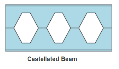
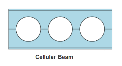
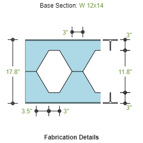
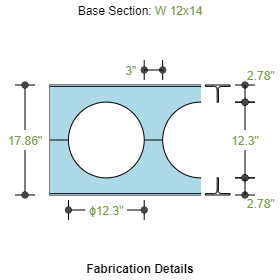
Castellated or Cellular Beams are defined as expanded beams fabricated with web openings. Castellated Beams have hexagonal openings whereas the cellular beams have circular openings. The section depth expansion with web opening provides material saving and the openings enable services to pass through. The design of the expanded beam involves a bit of complex process and ECPLUS follows the guidelines stipulated in AISC Design Guide 31.
Castellated/Cellular Beams are typically used for spans more than 10m(33ft) to take the advantage of increased moment of inertia due to the expansion of section depth without increasing the section weight.
Features
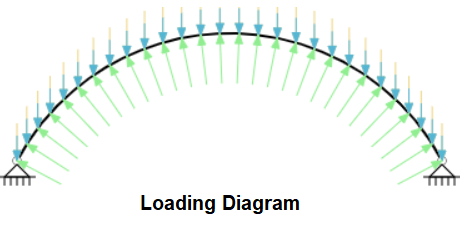
- ECCBEAM is used to design the castellated and cellular beamS of various shapes for Dead, Live, Snow and Wind loads and combinations.
- Design Standards
- American (AISC 360-16) – LRFD
- American (AISC 360-16) – ASD
- Section
- Standard Table: American, British and European Shapes
- user Defined Section
- Span
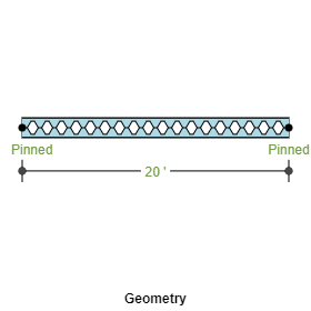
- Straight Beam
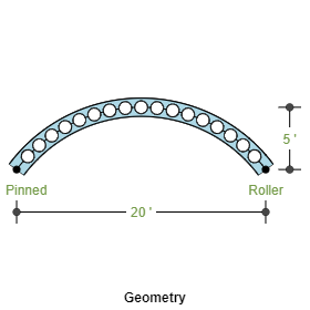
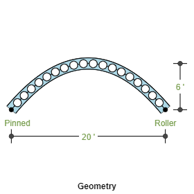
- Circular Beam (Arch Type)
- Parabolic Beam (Arch Type)
- Supports and Restraints
- Left Support: Pinned, Roller, Fixed and Roller
- Right Support: Pinned, Roller, Fixed and Roller
- Define Effective Buckling Length
- Fabrication
- Castellated Type
- Cellular Type
- Loads
- Define Dead Loads: Selfweight is calculated by Program
- Define Collateral Loads: Additional Dead Loads due to fixtures
- Define Snow Loads
- Define Wind Loads: Upto 12 cases of wind loads
- Combinations
- Auto Load Combination: Program automatically generates load combinations according to the design standard selected
- SLS Load Combinations
- ULS Load Combinations
Design Considerations
- Axial Compressive Strength: The axial compression in Tee section is calculated using the global moment and the lever arm distance between the Tee's plus the axial force at the section under consideration
- Flexural Strength of Tee Section: The flexural capacity of Tee section is calculated considering the lateral bukcling, slenderness of the elements and compared to the vierendeel moment due to openings
- Flexural Strength of Web Post: Moment is induced the web post due to difference in the axial force of subsequent Tee section. The flexural capacity of the web post is calculated using the design procedure (AISC design guide 31)
- Horizontal Shear in the web post: Horizontal shear in the web post is calculated and compared with its capacity
- Vertical Shear of Net and Gross Sections: Shear force at the net section and gross section is calculated and compared with its capacity
- Deflection: The deflection limits due to Live Load and Total Loads are calculated
References
- ANSI/AISC 360-16 – “Specification for Structural Steel Buildings”
- AISC Steel Design Guide 31 - "Castellated and Cellular Beam Design"
Revision
- Ver 1.0 - Initial Version
|
|
Download Sample Report |