Help Topics
ECCBEAM - Castellated and Cellular Beam Design

This part of user manual describes how to use ECCBEAM for the design of Castellated and Cellular Beams for straight, circular and parabolic shapes of spans. ECPlus applications are designed as wizard type which is a step by step guided input procedure. If you are new to ECPlus applications, click here for general guidance.
Prerequisites: The user is expected to have a basic understanding of structural steel design concepts.
The minimum input data required to use this application is as follows:
- ❶ Structural Steel Section and Grade.
- ❷ Span and Restraint Conditions.
- ❷ Castellated or Cellular Fabrication Details
- ❸ Loads and Combination.
Design Options
This page allows to select the design standard and unit.
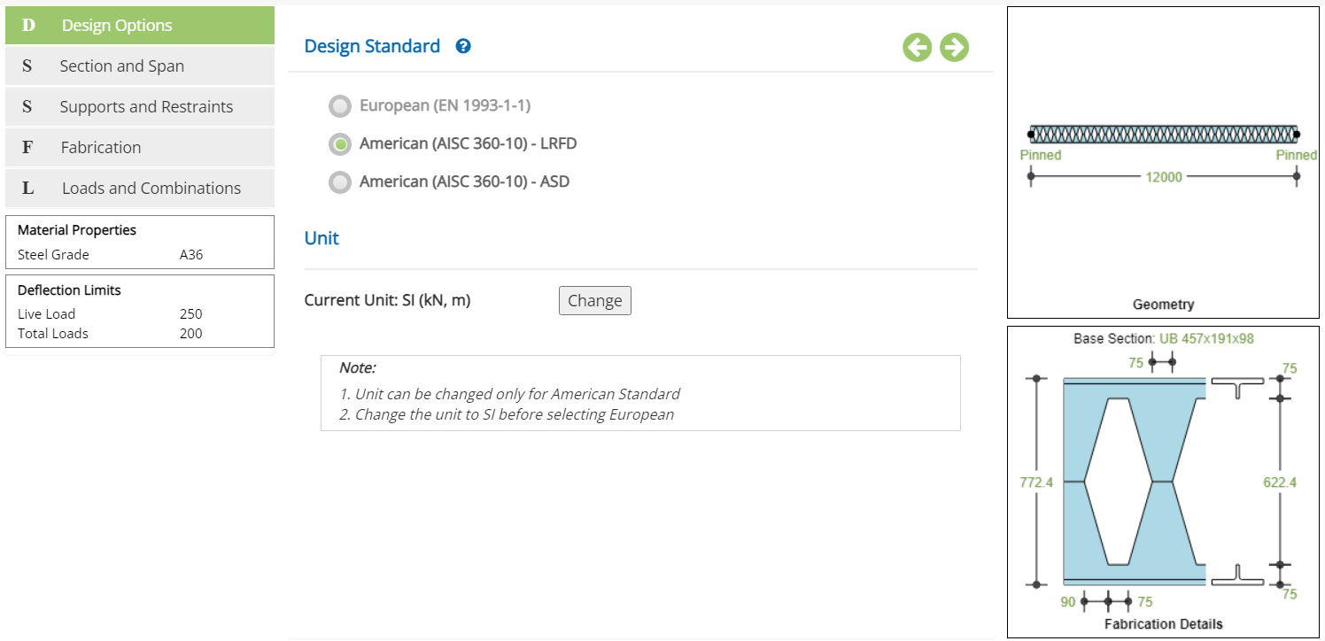
Design Standard
Select the National Standard for the design. Available Standards: ☉European, ☉American.
European Standard is not available in the current version.
Unit
It displays the active unit. The unit Change button is displayed when ☉American Standard is selected.
European Standard can not be selected when Imperial unit is active.
Change
Click this button to open the unit change pop-up dialog.
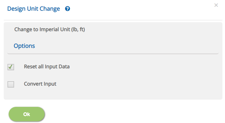
☐ Reset all Input Data
This option will reset the input data for the new unit. This option is recommended if the job is new and no input data has been entered yet.
☐ Convert Input
This option allows to convert previously entered input datas to the new unit.
Section and Span
This page allows to select the section size and the span details.
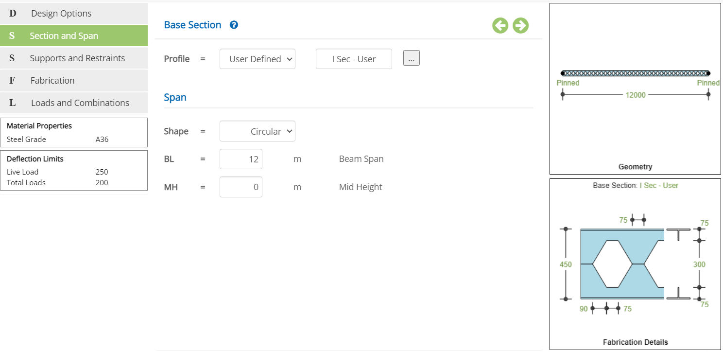 Shape
Shape▽ Straight: Select this option if the beam is straight.
▽ Circular: Select this option if the beam is circular shape.
▽ Parabolic: Select this option if the beam is parabolic shape.
Steel Section Table
By choosing the Type as Standard , the Cross-sectional properties will be displayed for the selected Section. To change the selected Section, click button, a pop-up dialog box displays a list of standard section based on option listed in menu Section Table & Cross Section
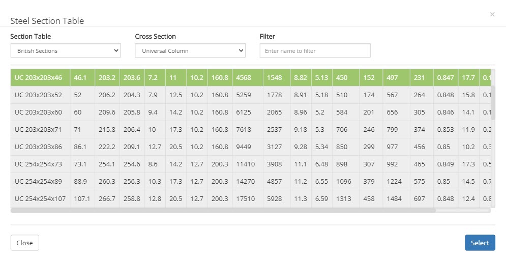 ▽ Section Table:
Select this option to have list of Standard British, European or AISC Sections.
▽ Cross Section:This option allows user to select wider or narrow flange beam like UB, UC, IPE, HE, W, M, etc., based on selection at Section Table menu.
▽ Filter:Based on name by user and with option selected at Section Table and Cross Section , a filtered member list will be displayed.
I Sec User
By choosing the Type as I Sec User , enter Cross-sectional properties.
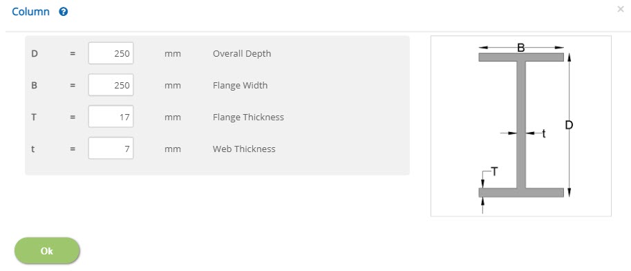 Overall Depth - D
Enter overall depth of the section.
↔ Range: 50 to 1500 mm (1.5 to 60 inches)
Enter the flange width of the section.
↔ Range: 50 to 1500 mm (1.5 to 60 inches)
Enter the thickness of flange of the section.
↔ Range: 3 to 100 mm (0.1 to 4 inches)
Enter the thickness of web of the section.
↔ Range: 2 to 100 mm (0.05 to 4 inches)
Enter the overall span of the steel beam.
↔ Range: 1 to 500 m (3.28 to 1640.42 ft)
Enter the height at the midspan in case the beam is Circular or Parabolic shape.
↔ Range: 0 to 100 m (0 to 328.08 ft)
Supports and Restraints
This page allows to enter the beam support conditions.
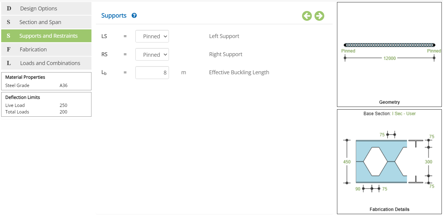 Left / Right Support - LS / RS
Select the typr of left / right support from the drop down list.
▽ Pinned: Select this option to choose pinned support.
▽ Roller: Select this option to choose roller support.
▽ Fixed: Select this option to choose fixed support.
▽ Free: Select this option to choose free support.
Enter the effective buckling length of the beam (Usually the length of the beam between the lateral restraints).
↔ Range: 0 to 50 m (0 to 164.04 ft)
Fabrication Type
This page allows to enter the beam fabrication details as castellated or cellular.
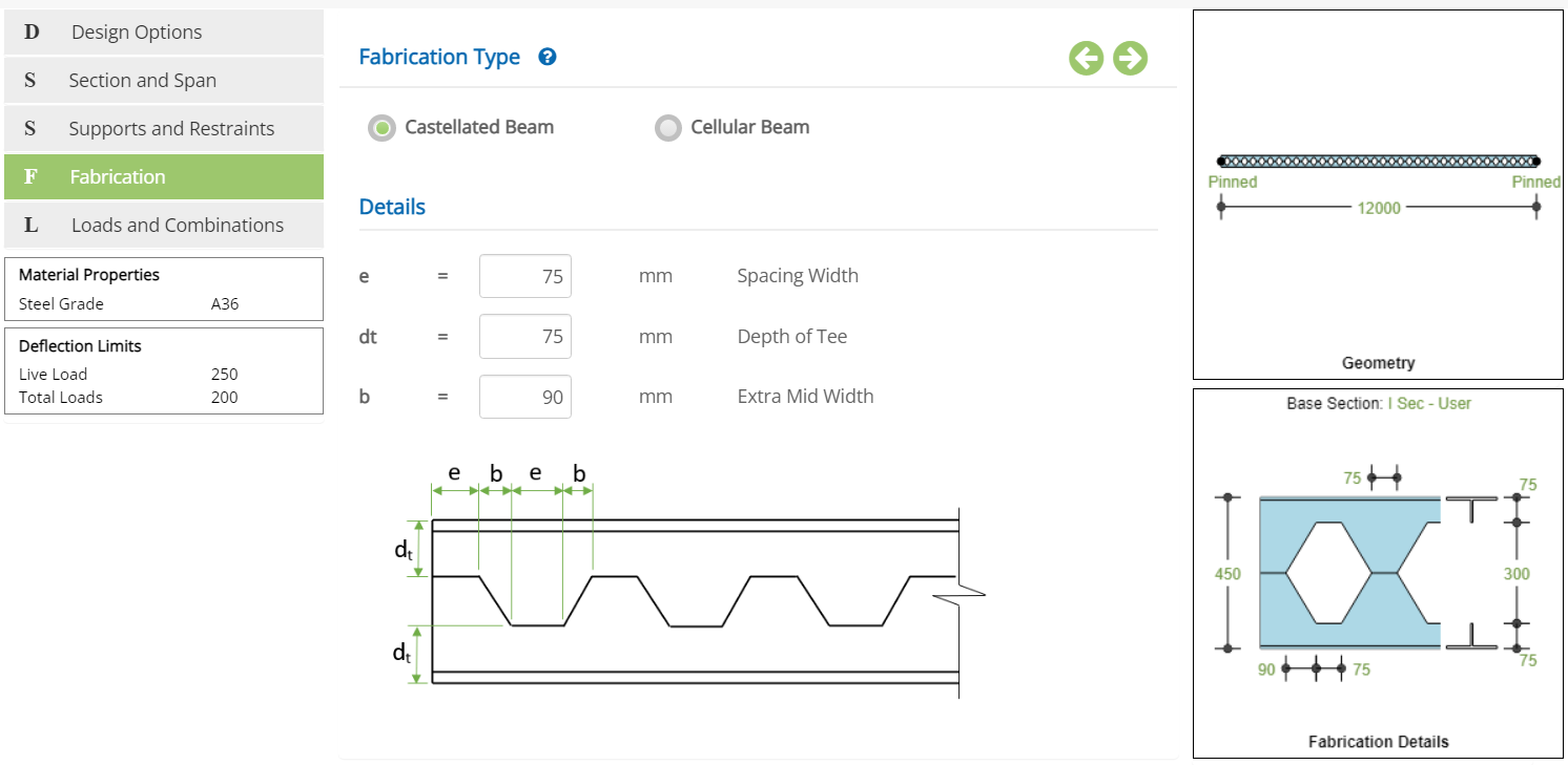
☉Castellated Beam: Select this option to design as castellated beam.
☉Cellular Beam: Select this option to design as cellular beam.
Fabrication - Castellated Beam
Spacing Width - eEnter width of the heaxgon opening as indicated in the picture.
↔ Range: 10 to 1000 mm (0.39 to 39.37 in)
Enter the depth of the tee portion.
↔ Range: 3 to 2000 mm (0.12 to 78.74 in)
Enter extra mid width of the hexagon opening as indicated in the picture.
↔ Range: 10 to 1000 mm (0.39 to 39.37 in)
Fabrication - Cellular Beam
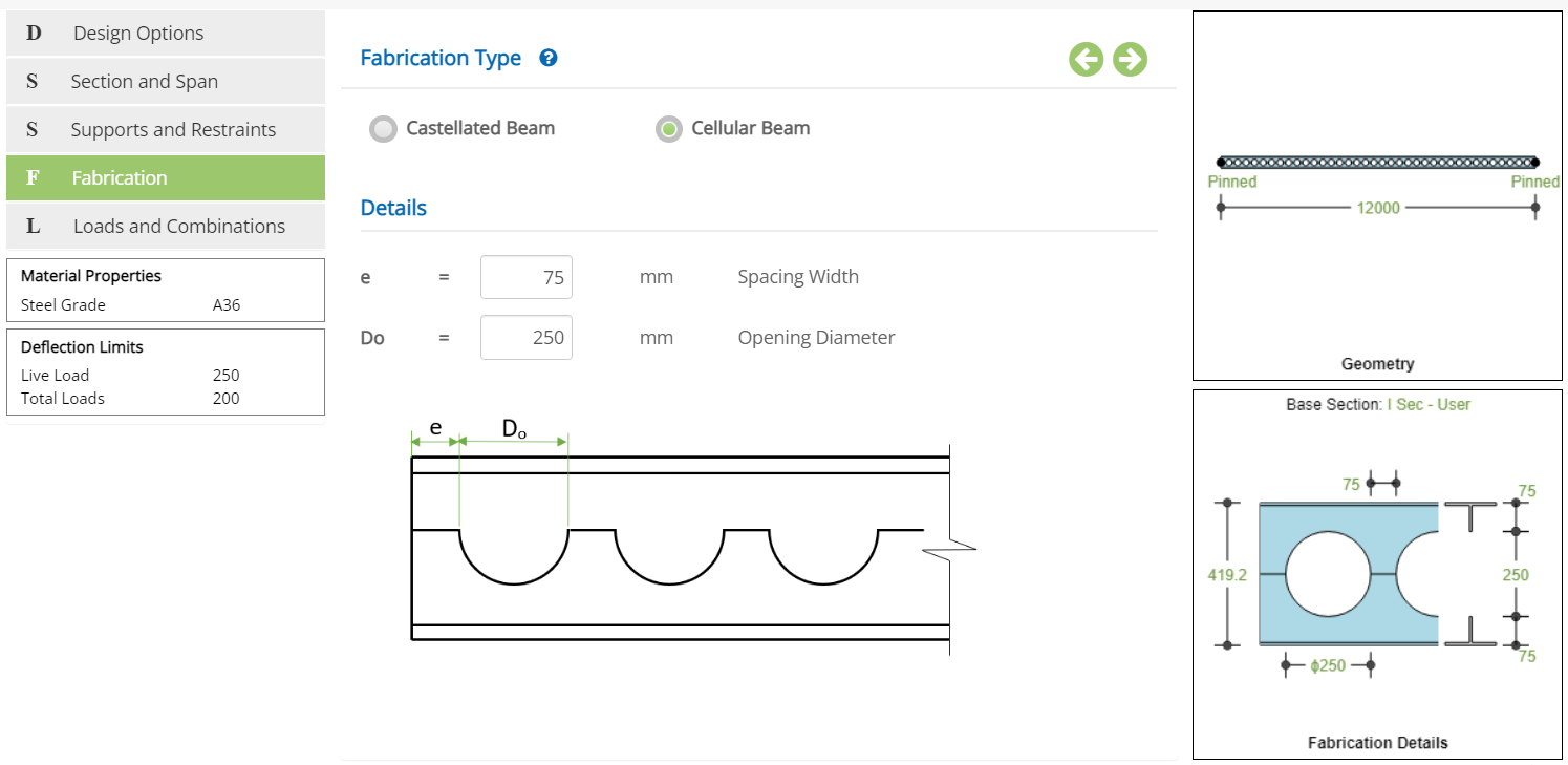 Spacing Width - e
Enter width of the spacing provided.
↔ Range: 10 to 1000 mm (0.39 to 39.37 in)
Enter the diameter of opening for the cellular beam.
↔ Range: 10 to 2000 mm (0.39 to 78.74 in)
Loads and Combinations
This page allows to provide the load and load combination details for the design.
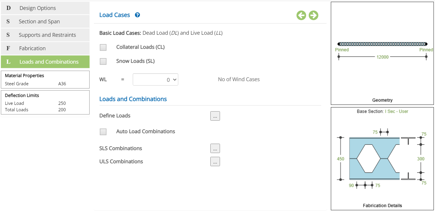
☐ Collateral Loads (CL): Check this option to include collateral loads into the design.
☐ Snow Loads (SL): Check this option to include snow loads into the design.
▽ No of Wind Cases - WL: Select the number of wind load cases available from the drop down menu.
☐ Auto Load Combinations: On checking this option, program will automatically generates service and ultimate load combinations.
Define Loads
Click button to open the pop-up dialog to define the load details. This is a spreadsheet type input dialog - right click to add or delete rows. Alternatively, the user can copy and paste the data from an external source such as Microsoft Excel.
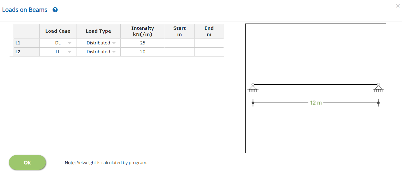
▽ Load Case: Select the load case from the drop down.
▽ Load Type: Select load type as either distributed or point load from the drop down menu.
Enter the intensity of the load with respect to the load case and type. The directions are vertical for all load types except Wind loads. For wind loads, the direction of the loads is vertical direction of the beam in case of circular and parabolic shape beams.
Start / EndEnter the start / end location of the corresponding load over the beam. Leaving the start cell blank assumes starting location as 0. Leaving the end cell blank assumes end location as horizontal length of the beam. For point loads, end location is not applicable. Leaving the start location blank for point load assumes the point load at midspan.
Service Load Combinations
Click this button to open the Service Load Combinations pop-up dialog. This is a spreadsheet type input dialog - right click to add or delete rows. Alternatively, the user can copy and paste the data from an external source such as Microsoft Excel.
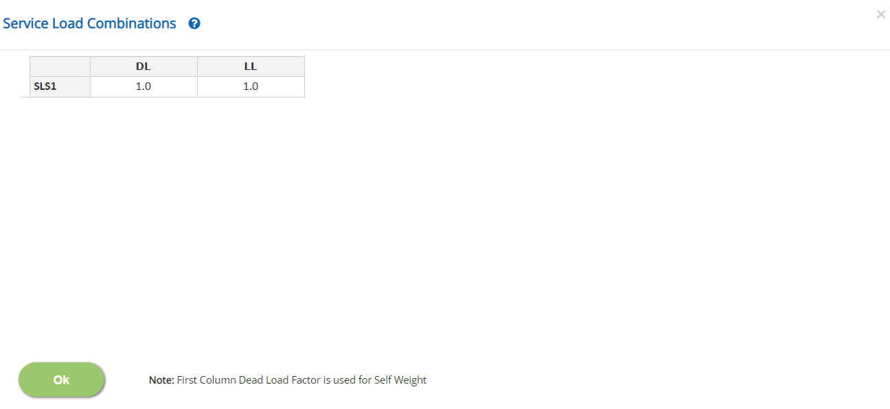
In this pop-up, n - number of Service Load Combinations (SLS) can be added with factors for each load case defined earlier.
Load Cases Factors
Load Case Description is displayed in each spreadsheet column. Enter the load factor for every load case and for each load combination.
↔ Range: -10 to 10
- Note 1: For Dead Load case type, which is the first column, the factor should be a positive non-zero value.
- Note 2: Service Load Combinations are also used for the design of the beam for ASD method.
Ultimate Load Combinations
click this button to open the Ultimate load Combinations pop-up dialog. This is a spreadsheet type input dialog - right click to add or delete rows. Alternatively, the user can copy and paste the data from an external source such as Microsoft Excel.
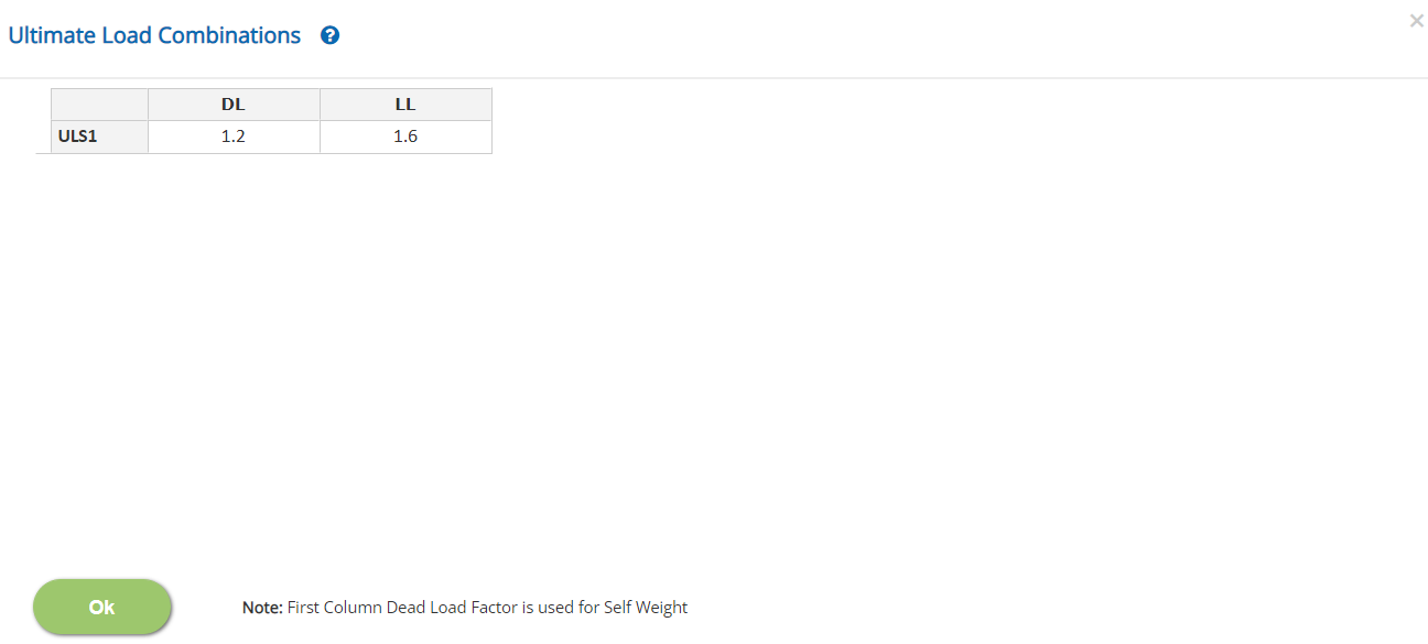
In this pop-up, n - number of Ultimate Load Combinations (ULS) can be added with factors for each load case defined earlier.
Load Cases Factors
Load Case Description is displayed in each spreadsheet column. Enter the load factor for every load case and for each load combination.
↔ Range: -10 to 10
- Note 1: For Dead Load case type, which is the first column, the factor should be a positive non-zero value.
- Note 2: Ultimate Load Combinations are only for LRFD Method for the design of the beam.
Design Setting
Setting for Design Data such as Material Properties and Deflection Limits are presented in this section. This setting pop-up can be accessed by clicking the bottom panel below the left navigation.
Material Properties
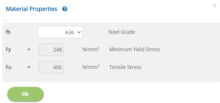
Steel Grade - fb
Select the grade of steel for the castellated/cellular beam from the drop down menu.
Minimum Yield Stress - Fy: Not editable for standard grade
↔ Range: 50 to 2000 N/mm2 (7.3 to 290.1 ksi)
Tensile Stress - Fu: Not editable for standard grade
↔ Range: 50 to 4000 N/mm2 (7.3 to 580.2 ksi)
Deflection Limits
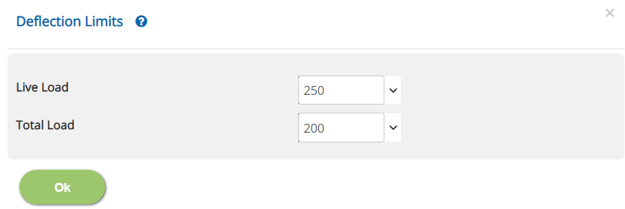
Live Load / Total Load: Span / Deflection Ratio
↔ Range: 10 to 2000
Error Handling
Errors and Warnings are generated to prevent any inadvertent error in the input data. This section describes how to handle the errors and warnings. These errors are displayed at the bottom of the input page when the data in one or more input fields invalidate each other. Calculation can not be run if there is any error in the input data.
- Note: Out of range errors are displayed next to the input field.
| # | Error | Reason | Solution |
|---|---|---|---|
| 1 | Warning: Lateral buckling length detected greater than 2.0 times of beam span | The Effective Buckling Length at Supports and Restraints page is specified more than two times the span of the beam. This warning is to alert the user that this is unsual. | Check the span of the beam or effective buckling length and make the changes if required. |
| 2 | Warning: Web outstand is inside the root radius of the Tee Section | The depth of the tee Fabrication Type page is specified such that the outstand of the web outstand is less than the root radius. | Modify the opening size or the depth of tee as required. |
| 3 | Warning: Web outstand is less than 2.0 times thickness of flange - flange may not be stiffened | The depth of the tee Fabrication Type page is specified such that the outstand of the web outstand is less than two times of the flange thickness. Such condition affects the way the elements are considered as stiffened | Modify the opening size or the depth of tee as required. |
| 4 | Error: The circular span shape exceeds semi circle | The mid height of the beam at Section and Span page is specified such that the circular shape exceeds semi circle. This is a limitation of the program calculation for the analysis and design of circular shape. | Adjust the mid height or the span so as to satisfy the condition. |
| 5 | Error: The parabolic mid rise shall not exceed 2.0 times Beam Span | The mid height of the beam at Section and Span page is specified such that the parabolic mid height exceeds two times of the beam span. This is a limitation of the program calculation for the analysis and design of parabolilc shape. | Adjust the mid height or the span so as to satisfy the condition. |
| 6 | Error: Zero or Negative Web Outstand in the Tee Section | The depth of the tee Fabrication Type page is specified such that the outstand of the web outstand is zero or negative (The depth of tee is less than or equal to flange thickness). | Adjust the depth of tee or opening size to satisfy the condition. |
| 7 | Error: e/tw = *** should be between 10 to 30 as per AISC Design Guide 31 Clause 3.4 | The opening details at Fabrication Type page is specified that this design requirement is violated. This is the limitation of the program design as per AISC Design Guide 31 for castellated type. | Adjust opening details to meet the criteria. |
| 8 | Error: 2h/e = *** should be ≤ 8 AISC Design Guide 31 Clause 3.4 | The opening details at Fabrication Type page is specified that this design requirement is violated. This is the limitation of the program design as per AISC Design Guide 31 for castellated type. | Adjust opening details to meet the criteria. |
| 9 | Error: θ = *** should be 43 to 62 AISC Design Guide 31 Clause 3.4 | The opening details at Fabrication Type page is specified that this design requirement is violated. This is the limitation of the program design as per AISC Design Guide 31 for castellated type. | Adjust opening details to meet the criteria. |
| 10 | Error: S/Do = *** should be 1.08 to 1.5 AISC Design Guide 31 Clause 3.4 | The opening details at Fabrication Type page is specified that this design requirement is violated. This is the limitation of the program design as per AISC Design Guide 31 for cellular type. | Adjust opening details to meet the criteria. |
| 11 | Error: dg/Do = *** should be 1.25 to 1.75 AISC Design Guide 31 Clause 3.4 | The opening details at Fabrication Type page is specified that this design requirement is violated. This is the limitation of the program design as per AISC Design Guide 31 for cellular type. | Adjust opening details to meet the criteria. |