> >
Mat Foundation Design
|
|
Download Sample Report |
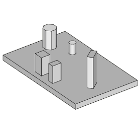
A Mat Foundation also known as a Raft is a rigid concrete footing to support loads from single or multiple columns (pedestals). Generally mat foundations are rectangular in shape, however, non-rectangular shapes are not uncommon. It is used where it becomes necessary to combine foundations of individual columns or walls either due to low bearing capacity or columns are too close to each other. Mat Foundation is also frequently adopted to reduce differential settlement effect. The thickness of a mat should be sufficiently thick to achieve rigidity and to allow linear distribution of soil bearing pressure.
The scope of this calculation module is to carry out analysis and design of a rectangular mat foundation with single or multiple pedestals for Service (SLS) and Ultimate (SLS) design loads. Bearing pressure and stability checks are carried out for serviceability loads. Pad and pedestal reinforcement are checked for ultimate design loads.
Features
- Batch Analysis for Multi Loads Set New
- Minimum soil cover can be specified when full soil cover is not guaranteed due to any expected adjacent excavations.
- Ground water table buoyancy effect on stability and design.
- Parametric modeling of pedestals and group design of pedestals used at different locations.
- Graphical edit option is provided for quick sizing and positioning of pad and pedestals without clash and overstep.
- Pedestal shape in rectangular, square, circular, octagon and wall with reinforcement design as optional.
- Pedestal Type as 'Pedestal', 'Loaded Area Top' and 'Loaded Area Bot' to simulate the support conditions from the analysis.
- Pedestals can be rotated in plan.
- Unlimited load cases and combinations for the design of pad and pedestals.
- Torsional stability and torsion reduced sliding resistant checks (Optional).
- Passive soil resistance on Pad and Pedestal (Optional).
- Allowable stability factors, increase or decrease in safe bearing capacity and crack width check for each serviceability combinations.
- Loads and Load Combinations can be easily imported from Microsoft Excel through clipboard or STAAD input file.
- Different Sign Convention such as STAAD Reactions, Forces and Module Standard for importing Loads from popular structural analysis software.
- Crack width check for pad at top and bottom for individual serviceability combinations (Optional).
- Comprehensive design report and summary results.
Design Considerations
- Self-weight of soil, pad and pedestal is automated by program. Dead Load factor is used as self-weight factor.
- Unfactored and factored loads on each pedestal location is calculated based on the factors defined in SLS and ULS combinations.
- Stability factors (overturning, sliding, uplift and SBC) for each combination is compared with allowable values.
- Pad section crack width is checked for service moment at critical location of pad on two faces (top and bottom) in both directions.
- Pad and pedestal design check is carried out when reinforcement design check is required.
- Moment capacity of pad is checked for both directions and top and bottom for ULS combination.
- One-way shear (Wide Beam Shear) is computed at the distance from pedestal face of each location in both directions. Critical ULS combination and location is reported.
- Two-way shear (punching shear) is checked at column face with maximum allowable shear stress and at the distance from pedestal face against concrete shear capacity.
- For all pedestals, axial load and biaxial moment capacity is compared with applied load and moment of each ULS combinations.
- Pedestal tie spacing is calculated for applied shear force and according to the maximum spacing allowed by the design code requirement.
National Standards Available
British Standard
European Standard
- National Annex of several countries such as Europe (Recommended), UK, Finland, Ireland, Malaysia, Norway, Singapore, Sweden are considered.
- Additionally, an option is provided to define the coefficients directly by the user.
American Standard
- The calculation allows the user to design the section in both imperial and metric units.
References
- BS 8110-1:1997 - Structural use of concrete - Part 1: Code of practice for design and construction.
- EN 1992-1-1:2004 - Design of concrete structures - Part 1-1: General rules and rules for buildings.
- ACI 318-14 - Building Code Requirements for Structural Concrete.
- ACI-224R-01 - Control of Cracking in Concrete Structures.
- STAAD or (STAAD.Pro) is a structural analysis and design software application by Bentley Systems
Revision
- Ver 2.1 - Batch Analysis for multiple loads set
- Ver 2.0 - European and American Design Standard included
- Ver 1.0 - Original version
|
|
Download Sample Report |