> >
Pinned Baseplate Design
| Download Sample Report |
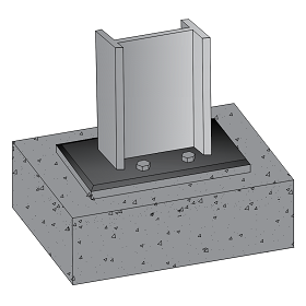
The scope of this calculation module is to design pinned base plates for axial load, transferred from a steel column to foundation concrete with no moment. Axial load can either be tensile or compressive in nature. The tensile force is dispersed to the foundation concrete with the help of holding down bolts and anchor plates.
Base Plate Thickness
Base plate dimensions are assumed based on a trial & error method, where by the area of base plate provided is compared against the required area for the load specified. Base plate area required is computed using the concrete bearing stress as follows,
Areq = F / (0.6 * Concrete cube strength)
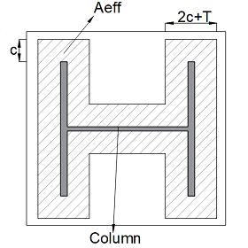
Effective area method is used for computing the thickness of base plate as follows, The projection ‘c’ is computed using base plate area required,
I-Section, Areq = 4c2 + c * column perimeter + column area
RHS-Section, Areq = mean wall perimeter length * (Section thickness + 2c)
SHS-Section, Areq = mean wall perimeter length * (Section thickness + 2c)
Base plate thickness, tp = c * √((3 * (0.6 * Concrete cube strength)) / (Plate design strength))
Forces Acting
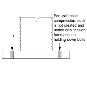
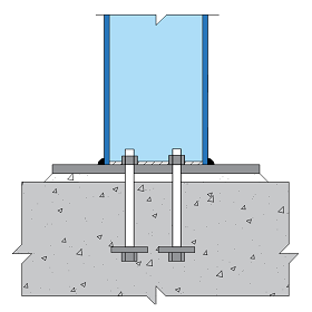
For pinned connections no moment is transferred, hence compression block is not created and only tension force acts on the holding down bolts during uplift which is resisted by the bolt tensile capacity. Holding down bolt checks the tensile capacity of bolts taking into consideration bolt grade, yield strength and tensile area of bolts as follows,
Bolt grade 4.6, Pb = 0.6 * Pt * 0.875 * At
Bolt grade 8.8, Pb = 0.8 * Pt * 0.875 * At
where,
Pt = Yield strength of bolt
At = Tensile area of bolt
Features
- An option is given for the user to choose the steel sections of their choice such as,
- I section
- Universal beam
- Universal column
- Rectangular hollow section
- Square hollow section
- Welded section (user defined)
- Bolt anchorage.
- Bolt with Plates
- The application calculates the anchor capacity based on the bolt and anchor plate properties defined where, anchor plate dimensions can also be edited by the user.
- Other Bolts
- The application allows the user to directly input the anchorage capacity of bolts.
Design Considerations
- The column is assumed to be concentric to the base plate.
- All welds are fillet welds and the weld strength relate to the minimum strength of the connected parts and the class of weld used.
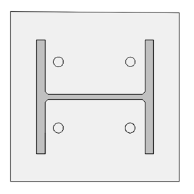
- The bolts are doubly symmetrical and are spaced along the width of the base plate.
- The minimum size of welds shall not be less than 3 mm and not be greater than the thickness of the flange in case of I sections and section thickness in case of rectangular hollow or square hollow section.
- The base plate area required is determined relative to maximum bearing pressure, the design strengths of column, base plate is determined corresponding to the steel grade and member thickness.
- If the axial load is compressive, projection ‘c’ is calculated corresponding to the column cross section.
- The thickness of base plate is calculated by effective area method that suggests an empirical formula for minimum thickness of the base pate.
- Holding down bolts are designed either by punching shear approach or by determining the pull-out capacity of cone of the foundation concrete.
- The punching shear approach used assumes a reinforced base, whereas the cone pull-out approach is appropriate for unreinforced base.
National Standards Available
British Standard
References
- BS 5950-1:2000 Code of practise for design - Rolled and Welded connections.
- BCSA publication “Joints in Steel construction - Simple Connections”.
- BCSA publication “Joints in Steel construction - Moment Connections”.
Revision
- Ver 1.0 - Original version