> >
Vertical Vessel Foundation Design
|
|
Download Sample Report |
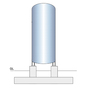
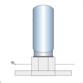
The scope of this calculation module (ECVERVES) is to analysis and design of a vertical vessel foundation with single or multiple pedestals for Serviceability (SLS) and Ultimate (ULS) load combinations. Bearing pressure and stability checks are carried out for serviceability loads. Pad (footing) and pedestal reinforcements are checked for ultimate loads.
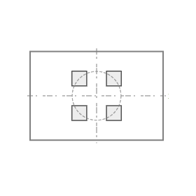
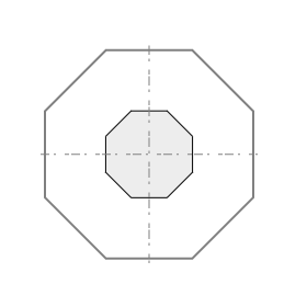
ECVERVES application is used to design pedestal (square, circle and octagon) and footing (square, rectangle, circle and octagon) with different shapes. For multiple pedestal options, pedestal shape restricted to square only.
Features
- This program needs a very limited available information from the user at any stage of the Project Phases (Proposal or FEED or Detail Engineering or EPC Phases of the Project) to design foundations.
-
The vertical vessel foundation analysis and design can be done by following options,
- Single pedestal with all footing shapes (square, rectangle, circle and octagon).
- Multi pedestal with square or rectangular footing.
- The user input loads are guided by predefined input field as defined in User Interface Input with a provision for eccentric loads and moments as recommended by PIP.
- The total equipment load inputs are automatically distributed to pedestal for multiple pedestals by program.
- Wind and Seismic load calculation are calculated automatically by the program based on selection of country code for the design.
- Wind and Seismic load (shear and moment) calculation are also entered manually based on input by the User or Vendor.
- Wind and Seismic loads can be used by Program simultaneously using by User/Vendor option as well by the Program Option to compare both values and design without any compromise on the quality of input from the Vendors.
- Automatic multiple Load Combination are generated by program based on selection of country code for the design.
- Additional load combinations are also automatically generated by program based on the percentage of increase in empty, operating and test weight. It means that as per user selection of country code, a list of basic load combinations for original loads and one more set of load combinations for the increased loads. Based on this opportunity, the program will define critical load combination without any ambiguity/confusion.
- A provision to specify minimum soil cover is available in case full soil cover cannot be guaranteed due to any expected adjacent excavations.
- Ground water table buoyancy effect on stability and design is available.
- User can specify the allowable stability factors and increase or decrease in SBC (Test, Wind and Seismic).
- Loads and Load Combinations can be easily imported from Microsoft Excel through clipboard facility.
- Crack width for pad at top and bottom is checked as an option for each serviceability combinations.
- Facility to check the anchorage capacity and interaction ratio for anchor bolts.
- Comprehensive design report and summary results. A step-by-step design calculation report eliminates any requirements for additional validation of the calculation.
Design Considerations
- Loads on the pedestal for multiple pedestal case, automatically calculated by program based on the location of pedestals.
- Self-weight of soil, pad and pedestal is considered by program. Dead Load Factor is used as self-weight factor
- Un-factored and factored loads on each pedestal location is calculated based on the SLS and ULS combinations.
- Stability factors (overturning, sliding, uplift and SBC) for each load combination are compared with allowable factors (generated by program).
- Pad section crack width is checked for service moment at critical location of pad on two faces (top and bottom) in both directions.
- Moment capacity adequacy is checked for both directions and top and bottom with critical ULS combination.
- One-way shear (Wide Beam Shear) is computed at “d” distance from pedestal face of each location in both directions. Critical ULS combination and location reported.
- Two-way shear (punching shear) is checked at recommended distance based on the design standard. For British, column face with maximum allowable shear stress and at ”1.5d” distance from pedestal face against concrete shear capacity. For European and American at ”2.0 d” distance and ”0.5 d” distance from pedestal face against concrete shear capacity respectively.
- For both pedestals, axial load and biaxial moment capacity compared with design load and moment of each ULS combinations.
- `Pedestal tie spacing is computed based on the total lateral force over the section compared with maximum allowable spacing.
National Standards Available
British Standard
Euro Standard
- National Annex of several countries such as Europe (Recommended), UK, Finland, Ireland, Malaysia, Norway, Singapore, Sweden are considered.
- Additionally, an option is provided to define the coefficients directly by the user.
American Standard
- The calculation allows the user to design the section in both Imperial and metric units.
References
- BS 8110-1:1997 – Structural use of concrete – Part 1: Code of practice for design and construction.
- EN1992-1-1:2004 - Design of concrete structures - Part 1-1: General rules and rules for buildings.
- ACI 318-14 - Building Code Requirements for Structural Concrete.
- ACI-224R-01 – Control of Cracking in Concrete Structures.
Revision
- Ver 1.0 - Original version
|
|
Download Sample Report |