Help Topics
ECVERVES - Vertical Vessel Foundation Design
This part of user manual describes how to use ECVERVES for the design of Vertical Vessel Foundations with a single or multi pedestals. ECPlus applications are designed as wizard type which is a step by step guided input procedure. If you are new to ECPlus applications, click here for general guidance.
Prerequisites: The user is expected to have a basic understanding of foundation design concepts.
The minimum input data required to use this application is as follows:
- ❶ Soil data such as Safe Bearing Capacity, Density of Soil, Angle of Internal Friction, Co- efficient of internal friction between bottom of foundation/soil, Ground Water Table and other soil parameters, reinforced concrete properties, Allowable Stability Safety Factors, etc., which are to be defined in the reinforced settings by the User
- ❷ Design Options
- ❸ Vessel Geometric Data
- ❹ Pedestal and footing / pad information
- ❺ Design parameters for environmental design loads such as wind and seismic, as per country code requirements
Design Options
This page allows to select the foundation support system, i.e. soil or pile, design standard and unit.
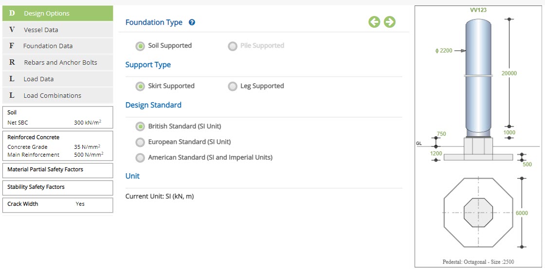
Foundation System
Select if the foundation is supported on Soil or Pile
Support Type
Select if the support type is Skirt or Leg supported
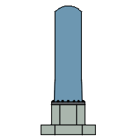
▽ Skirt Supported: Vessel supported ove the skirt.
▽ Leg Supported: Vessel supported ove the legs.
Design Standard
Select the National Standard for the design. Available Standards: ☉British, ☉European and ☉American.
Unit
It displays the active unit. The unit Change button is displayed when ☉American Standard is selected.
British and European Standards can not be selected when Imperial unit is active.
Change
Click this button to open the unit change pop-up dialog.
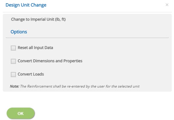
☐ Reset all Input Data
This option will reset the input data for the new unit. This option is recommended if the job is new and no input data has been entered yet.
☐ Convert Dimensions and Properties
This option allows to convert all the previously entered input data except Load data to the new unit.
☐ Convert Loads
This option allows to convert previously entered load data to the new unit.
Note: Both Convert Dimensions and Properties and Convert Loads options can be used simultaneously to convert all the previously entered input values to the new unit.
- Note: While the program attempts to reasonably convert the rebar sizes equivalent to the new unit, the user should verify the reinforcement pages of pad and pedestal to ensure that the conversion has been applied as expected.
Incorrect option leads to out of range errors and should be manually corrected.
Vessel Data
This page allows the input of vessel data such as vessel number, vessel dimensions and corrosion allowance.
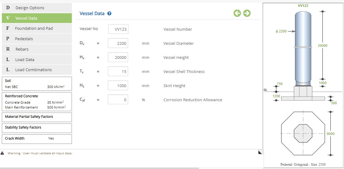
Skirt Supported
Vessel Number - Vessel NoEnter the vessel number.
Vessel Diameter - DvEnter the overall diameter of the vessel.
↔ Range: >= 20 mm (>= 20 inches)
Enter the total height of the vessel which includes TL to TL + Shell top part.
↔ Range: >= 100 mm (>= 80 inches)
Enter the shell thickness of the vessel.
↔ Range: 0 to 100 mm (0 to 4 inches)
Enter the skirt height of the vessel.
↔ Range: >= 100 mm (8 to 400 inches)
This will allow the program to reduce the self weight of the vessel in the calculation based on input.
↔ Range: 0 to 100 % (0 to 4 %)
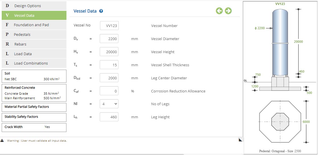
Leg Supported
Leg Center Diameter - DlcdEnter the leg center diameter.
↔ Range: >=100 mm (>=4 inches)
Select the number of supported legs form the drop-down menu. Number of legs available are, ▽ 3 ▽ 4 ▽ 6 and ▽ 8
Leg Height - LhEnter the height of the supported leg.
↔ Range: 150 to 6000 mm
Foundation and Pad
This page allows the input of foundation and pad data such as foundation depth, footing geometry and soil cover.
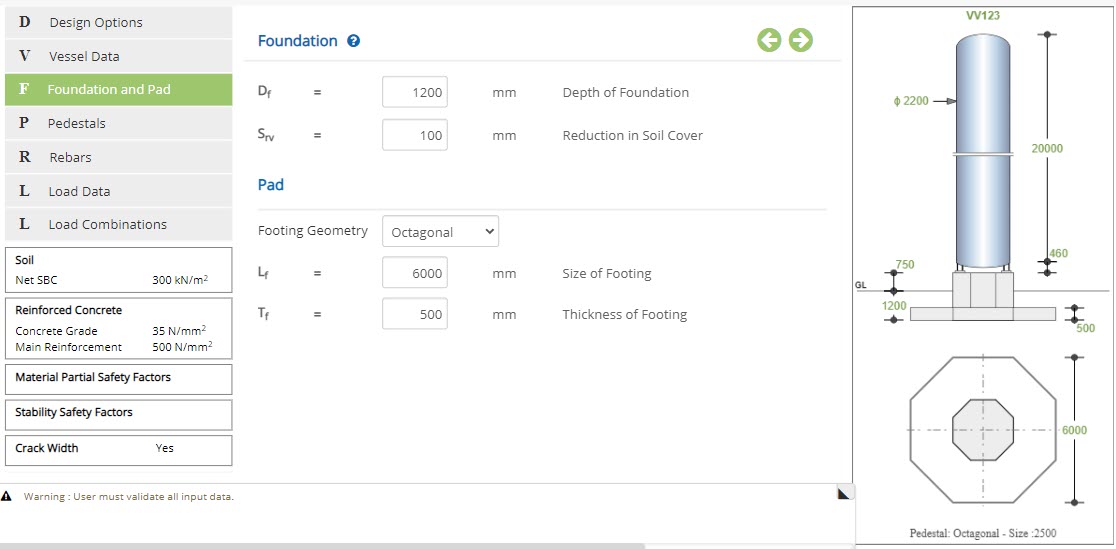 Depth of Foundation - Df
Enter the depth of the foundation.
↔ Range: 300 to 6000 mm (12 to 250 inches)
Enter the reduction in soil cover.
↔ Range: 0 to 5000 mm (0 to 200 inches)
▽ Square: Select this option to use square footing.
▽ Rectangular: Select this option to use rectangular footing.
▽ Octagonal: Select this option to use octagonal footing.
▽ Circular: Select this option to use circular footing.
Size of Footing - Lf
Enter the size of the footing, for square, circular or octagonal shape.
↔ Range: 1000 to 15000 mm (40 to 600 inches)
Enter the length and breadth of the footing correspondingly.
↔ Range: 1000 to 15000 mm (40 to 600 inches)
Enter the thickness of the footing.
↔ Range: 300 to 5000 mm (12 to 200 inches)
Pedestals
This page allows the input of pedestal data such as pedestal geometry and dimensions.
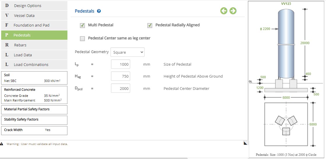
☐ Multi Pedestal: Select this option to use multiple pedestals.
☐ Pedestal Radially Aligned: Select this option to radially align the pedestal.
☐ Pedestal Center same as leg center: Select this option to use pedestal center diameter same as leg center diameter.
▽ Square: Select this option to use square pedestal.
▽ Octagonal: Select this option to use octagonal pedestal.
▽ Circular: Select this option to use circular pedestal.
Size of Pedestal - Lp
Enter the size of the pedestal.
↔ Range: 500 to 10000 mm (20 to 400 inches)
Enter the height of the pedestal over the ground level.
↔ Range: 0 to 6000 mm (0 to 250 inches)
Enter the pedestal center diameter.
↔ Range: >=100 mm (>=4 inches)
Rebars and Anchor Bolts
This page allows the input of cover, reinforcement and anchor bolt details.
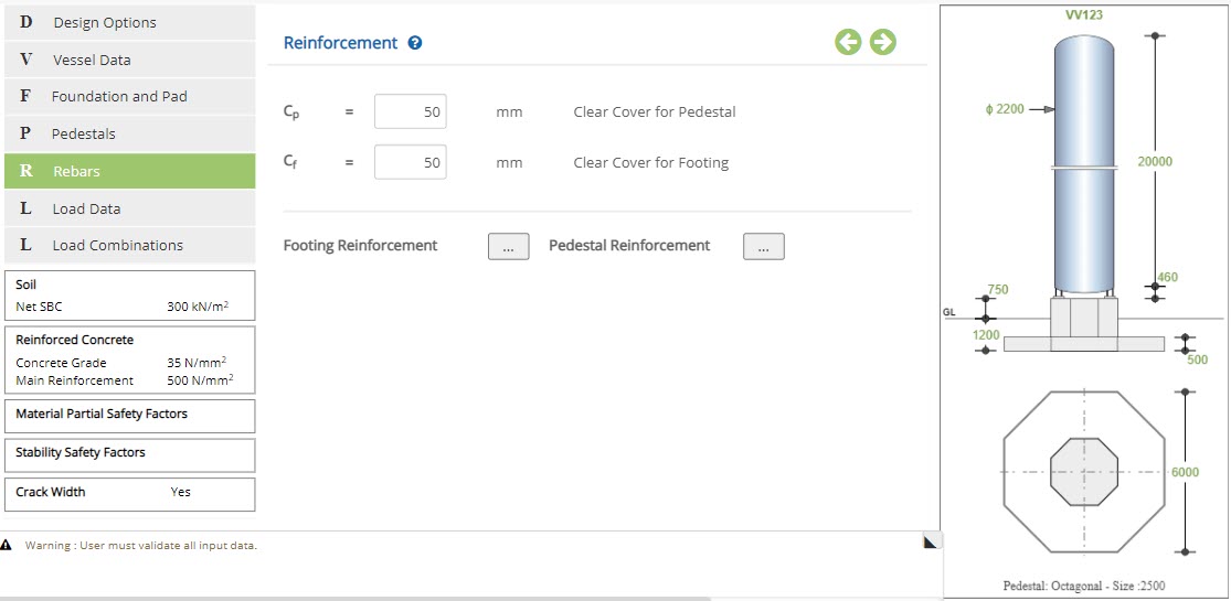 Clear Cover for Pedestal - Cp
Enter the clear cover for the pedestal.
↔ Range: 15 to 150 mm (0.5 to 6 inches)
Enter the clear cover for the footing.
↔ Range: 15 to 150 mm (0.5 to 6 inches)
☐ Check Anchor Bolts: Check this option to enable anchor bolt check.
Anchorage Tension Capacity - CtEnter the anchorage tension capacity of the bolts.
↔ Range: 0 to 1500 kN (0 to 1200 kips)
Enter the anchorage shear capacity of the bolts.
↔ Range: 0 to 1500 kN (0 to 1200 kips)
Footing Reinforcement - Rectangular / Square Footing
Click this button to open the pop-up dialog to define the footing reinforcement details.
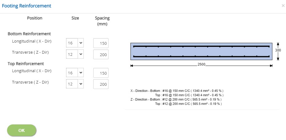 Size
SizeEnter or select the size of bottom and top reinforcement in both longitudinal and transverse directions.
↔ Range: 4 to 60 mm
Enter the spacing of bottom and top reinforcement in both longitudinal and transverse directions.
↔ Range: 20 to 450 mm (1 to 18 inches)
Footing Reinforcement - Circular / Octagonal Footing
Click this button to open the pop-up dialog to define the footing reinforcement details.
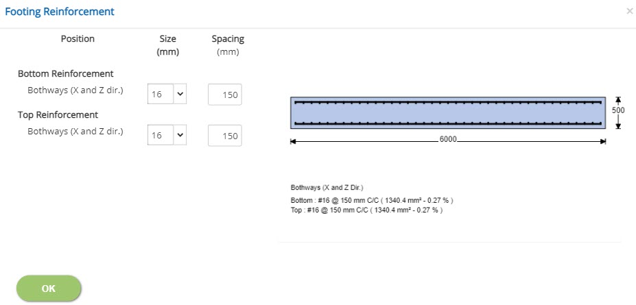 Size
SizeEnter or select the size of bottom and top reinforcement in bothways.
↔ Range: 4 to 60 mm
Enter the spacing of bottom and top reinforcement in bothways.
↔ Range: 20 to 450 mm (1 to 18 inches)
Pedestal Reinforcement
Click this button to open the pop-up dialog to define the pedestal reinforcement details.
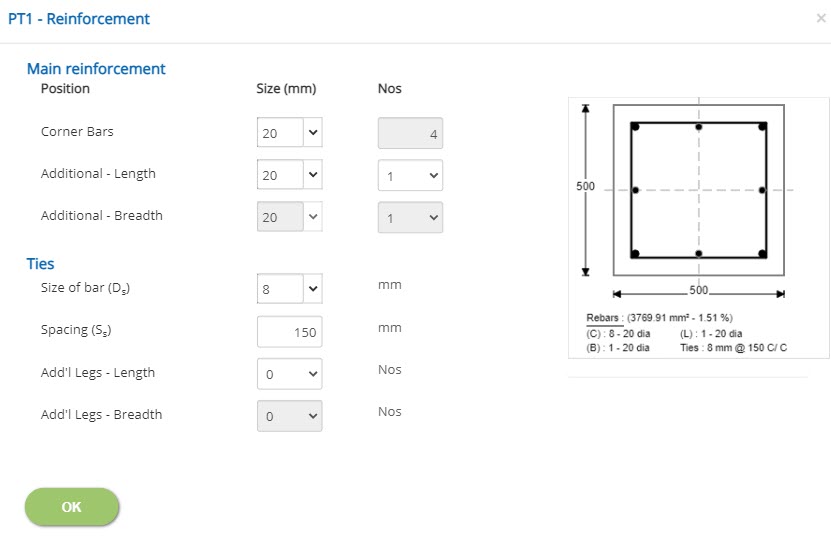
Main Reinforcement
SizeEnter or select the size of corner and additional bars in length and width directions.
NosSelect the number of bars in corner and additional bars in length and width directions.
Ties
Size of bar - DsEnter the size of bar for ties.
↔ Range: 4 to 60 mm
Enter the spacing of tie bars.
↔ Range: 20 to 450 mm (1 to 18 inches)
Select the number of additional legs in length and breadth directions correspondingly.
Anchor Bolts
Click this button to open the pop-up dialog to define the anchor bolt details.
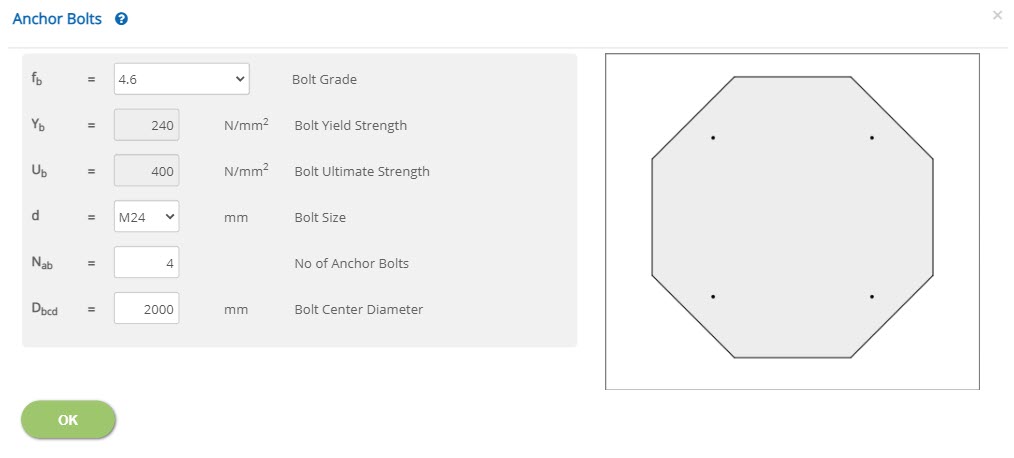 Bolt Grade - fb
Select the grade of the anchor bolt.
Bolt Yield Strength - YbDisplays the bolt yield strength based on bolt grade selected. For user defined bolt grade, enter value manually.
↔ Range: 10 to 1000 N/mm2 (1.5 to 145 ksi)
Displays the bolt ultimate strength based on bolt grade selected. For user defined bolt grade, enter value manually.
↔ Range: 10 to 1000 N/mm2 (1.5 to 145 ksi)
Bolt Size - d
Select the size of the bolt.
No of Anchor Bolts - NabSelect the number of anchor bolts.
Bolt Center Diameter - DbcdEnter the bolt center diameter.
↔ Range: >= 100 mm (>= 4 inches)
Load Data
This page allows user to enter load data for wind, seismic, vertical loads on the vessel. The wind and seismic loads are entered based on options (By User / Vendor, By Program, By Both or None) as per user choice. In addition, the user options are not limited to select any one country code or any one option. Example, the wind loads may be entered By User/Vendor option and at the same time the seismic load may be generated By Program or By Both option.
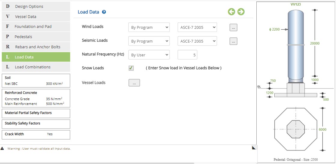 Wind / Seismic Loads
▽ By User / Vendor: Select this option to use wind / seismic loads By User / Vendor. If the information is readily available with user from vendor or any other source, the User / Vendor option is selected. In this case, the actual wind/seismic loads (shear and moment) are to be entered under Vessel Loads as applicable.
▽ By Program: Select this option to calculate wind/seismic loads automatically by the program. The required parameters to calculate automatically by the program are to be entered as per selected country code.
▽ By Both: Select this option to use loads by both user / vendor and program. In this option, the user is provided with both options to enter input. The program calculates and compares shear and moment values with user / vendor input. The maximum values are conservatively used for the calculation. However, based on comparison of user input and program calculated values, the user may take any appropriate decision either to proceed or comment any discrepancies to the vendor or inter-disciplines (source of input) to clarify / rectify before implementation.
▽ None: Select this option to run the calculation without wind or seismic loads as applicable.
▽ Code: Select the appropriate country code to use in case of by program option to calculate wind and seismic loads based on selection of applicable country code.
Wind Load by Program - BS 6399
Click this button to open the wind load by program popup based on British Standard BS 6399.
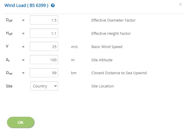 Effective Diameter Factor - Deff
Enter the effective diameter (Deff),factor.
↔ Range: 0.5 to 3
| Vessel Diameter (m) | Increase Factor |
| 0.5 - 1.0 | 1.60 |
| 1.0 - 1.5 | 1.37 |
| 1.5 - 2.0 | 1.28 |
| 2.0 - 2.5 | 1.20 |
| 2.5 and up | 1.18 |
| Spherical (any dia.) | 1.10 |
Effective Height Factor - Heff
Enter the effective height (Heff), factor.
↔ Range: 0.5 to 3
Enter the basic wind speed (V), as per design criteria as applicable to the country code. This value shall be carefully decided by the user based on customer input as applicable to the selected country code to avoid any mistake.
↔ Range: 10 to 500 m/s (30 to 1700 m/s)
Enter the site altitude (Δs) based on available information with reference to Mean Sea Level (MSL).
↔ Range: 10 to 500 m (0 to 1700 ft)
Enter the closest distance to sea upwind (Dsw) based on available input.
↔ Range: 10 to 500 m (6 to 700 km)
Select the site location. The available options are Country and Town.
Wind Load by Program - EN 1991
Click this button to open the wind load by program popup based on Euro Standard BS EN 1991.
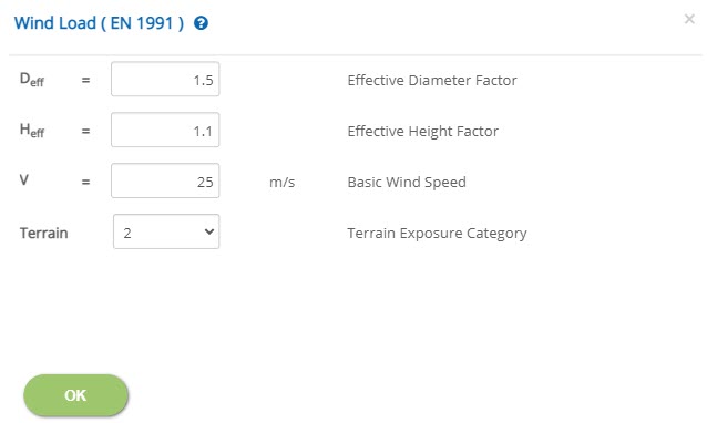 Effective Diameter Factor - Deff
Enter the effective diameter (Deff),factor.
↔ Range: 0.5 to 3
For factors refer 'Standard Diameter Factors' table
Effective Height Factor - HeffEnter the effective height (Heff), factor.
↔ Range: 0.5 to 3
Enter the basic wind speed (V), as per design criteria as applicable to the country code. This value shall be carefully decided by the user based on customer input as applicable to the selected country code to avoid any mistake.
↔ Range: 10 to 500 m/s (30 to 1700 ft/s)
Terrain Exposure Category
Select the terrain exposure category. The available options are 0, 1, 2, 3 & 4.
Wind Load by Program - ASCE 7
Click this button to open the wind load by program popup based on ASCE 7 - 2005, 2010 & 2016.
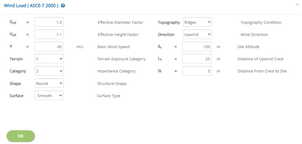 Effective Diameter Factor - Deff
Enter the effective diameter (Deff),factor.
↔ Range: 0.5 to 3
For factors refer 'Standard Diameter Factors' table
Effective Height Factor - HeffEnter the effective height (Heff), factor.
↔ Range: 0.5 to 3
Enter the basic wind speed (V), as per design criteria as applicable to the country code. This value shall be carefully decided by the user based on customer input as applicable to the selected country code to avoid any mistake.
↔ Range: 10 to 500 m/s (30 to 1700 ft/s)
Select the terrain exposure category. The available options are B, C & D.
Importance CategorySelect the importance category. The available options are 0, 1, 2, 3 & 4.
Structure ShapeSelect the shape of the structure.
Surface TypeEnter the type of the surface. The available options are Moderate Smooth, Rough and Very Rough Surfaces.
Topography ConditionSelect the topography condition. The available options are Ridges, Escarpments, Hill & Cliff.
Wind DirectionSelect the wind direction. The available options are up wind and down wind.
Site Altitude - ΔsEnter the site altitude (Δs) based on available information with reference to Mean Sea Level (MSL).
↔ Range: 10 to 500 m (30 to 1700 ft)
Enter the distance of upwind crest.
↔ Range: 10 to 500 m (30 to 1700 ft)
Enter the distance from crest to site.
↔ Range: 1 to 500 m (3 to 1700 ft)
Seismic Load by Program (ASCE / IBC)
Click this button to open the seismic load by program popup based on ASCE-7 – 2005, 2010 & 2016 AND IBC 2018.
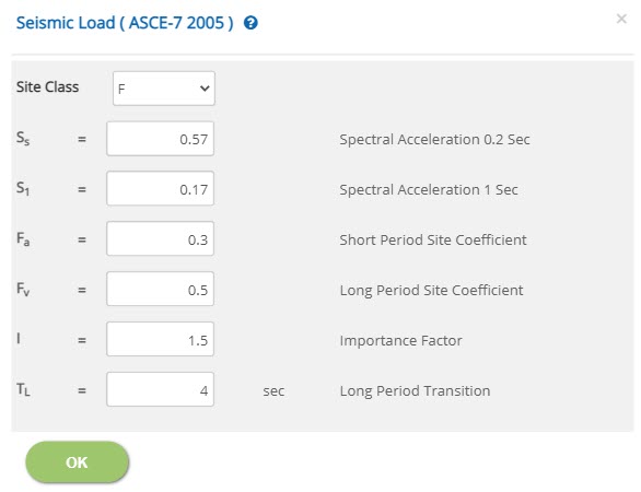 Site Class
Select the site class. The available options are A, B, C, D, E & F.
Spectral Acceleration 0.2 Sec - SsEnter the spectral acceleration at 0.2 second.
↔ Range: 0.2 to 10
Enter the spectral acceleration at 1 second.
↔ Range: 0.2 to 10
Enter the site coefficient for short period.
↔ Range: 0.1 to 5
Enter the spectral acceleration for long period.
↔ Range: 0.1 to 5
Enter the importance factor.
↔ Range: 0.5 to 5
Enter the long period transition.
↔ Range: 0 to 60 sec
Natural Frequency (Hz)
▽ By Program: Select this option to calculate natural frequency automatically by the program.
▽ By User: Select this option to enter natural frequency manually at the corresponding input.
↔ Range: 0.5 to 100 Hz
☐ Snow Loads: Check this option to consider any loads due to snow on the vessel. This check box facility is kept outside before to enter vessel load menu option in order to receive an input if applicable. If it is unchecked, the same shall not be editable by the user.
Vessel Loads
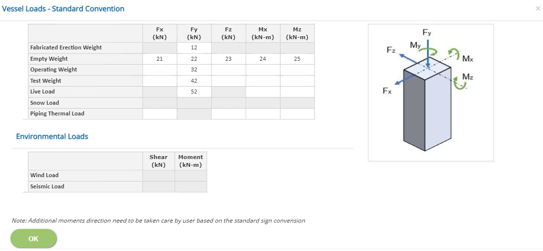 Fabricated Erection Weight - Df
Enter the fabricated erection weight (Dfa) for the vessel.
This eccentricity moment value is not allowed for erection load case.
↔ Range: -100000 to 100000
Enter the empty weight (De) of the vessel. The empty weight of the vessel excluding all attachments, trays, internals, insulation, fireproofing, agitators, piping, ladders, platforms, etc..,
Horizontal forces and additional moment due to eccentricity are allowed to calculation. Additional moment (Mx and Mz) direction need to reverify by user based on the standard sign convention.
↔ Range: -100000 to 100000
Enter the operating weight (Do) for the vessel, which includes the self-weight of the vessel plus the maximum weight of contents (including packing/catalyst) during normal operation. Operating weight of all vessel is entered in the input field against Fy.
Horizontal forces and additional moment due to eccentricity are allowed to calculation. Additional moment (Mx and Mz) direction need to reverify by user based on the standard sign convention.
↔ Range: -100000 to 100000
Enter the test weight (Dt) for the vertical vessel, which includes the self-weight of the vessel pus the maximum weight of test or cleaning contents during test case. This vertical load is entered in the input field against Fy.
Horizontal forces and additional moment due to eccentricity are allowed to calculation. Additional moment (Mx and Mz) direction need to reverify by user based on the standard sign convention.
↔ Range: -100000 to 100000
Enter the live load (L) for the vessel as per input based on platforms mounted on the vessel. Additional moment (Mx and Mz) direction need to reverify by user based on the standard sign convention.
The uniform area load is multiplied with effective platform area to apply as a concentrated load to enter against the input field Fy.
↔ Range: -100000 to 100000
Enter the total piping thermal load (Tsp) based on the expansion and contraction for pipes in the normal operating condition and enter the loads in the input field of Fx and Fz
Additional moment due to this lateral load is also to be calculated and applied in Mx and Mz
↔ Range: -100000 to 100000
Load Combinations
This page allows the user to select load combinations as per applicable country code.
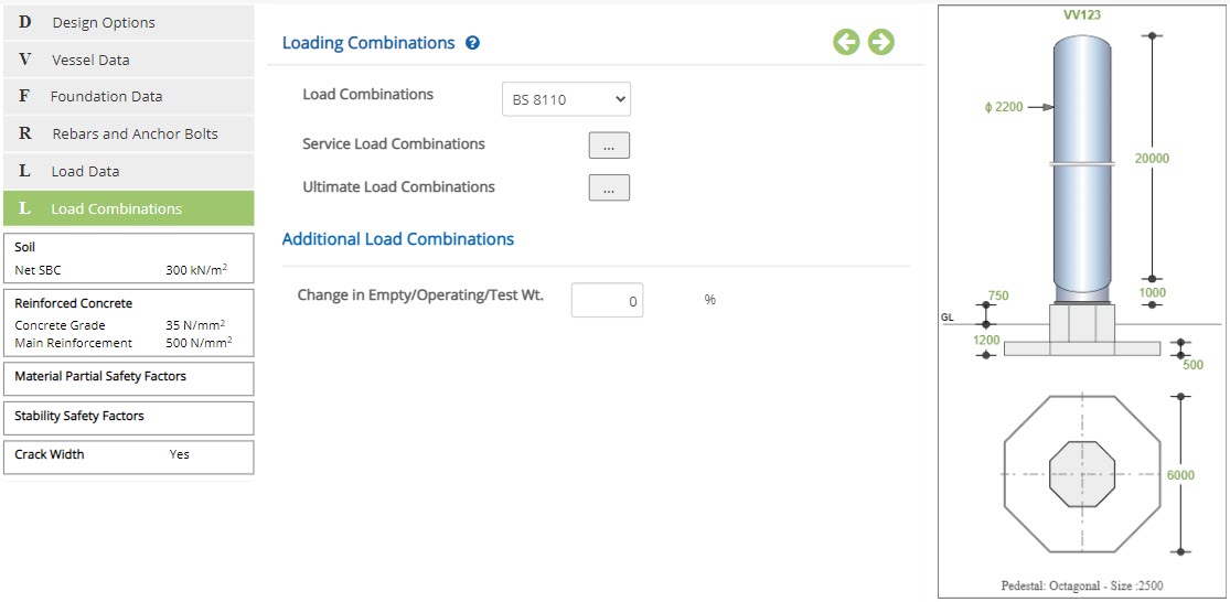 Load Combinations
Select the country code by which load combinations have to be considered. Select user-defined, to enter combinations manually, as per preference of the user.
The following are the list of country codes available for auto combinations:
- BS 8110
- EN 1992
- ASCE 2005
- ASCE 2010
- ASCE 2016
Enter the percentage of change in empty / operating and test weights to add additional load combinations. The default value of “zero” will ensure that no more additional combinations are added for checking. In case of non-zero values, additional load combinations are added as like original load combinations to design the foundation based on increased load weights.
↔ Range: 0 to 100 %
- Note: Based on the change in empty / operational / additional / test weight, SLS and ULS combinations will be created for the calculation in the back end of the program automatically. This unique facility helps to detect the critical load combination automatically by the ECVERVES for the present loads as well as increased loads.
Service Load Combinations
Click this button to open the pop-up dialog to define the service load combinations. This is a spreadsheet type input dialog - right click on the spreadsheet to add or delete rows. Alternatively, the user can copy and paste data from an external source such as Microsoft Excel.
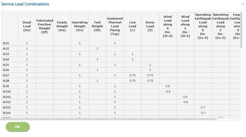
Displays the service load combinations as per the country code selected.
In case of different service load combination is required, the user-defined option is to be selected to create new service load combination as required by the user.
↔ Range: -10 to 10
- Note: For Dead Load case type, which is the first column, the factor should be a positive non-zero value.
Ultimate Load Combinations
Click this button to open the pop-up dialog to define the ultimate load combinations. This is a spreadsheet type input dialog - right click on the spreadsheet to add or delete rows. Alternatively, the user can copy and paste data from an external source such as Microsoft Excel.

Displays the ultimate load combinations as per the code selected.
In case of different ultimate load combination is required, the user-defined option is to be selected to create new ultimate load combination as required by the user.
↔ Range: -20 to 20
- Note: For Dead Load case type, which is the first column, the factor should be a positive non-zero value.
Design Setting
Setting for various Design Data such as Soil, Reinforced Concrete, Material Partial Safety Factors, Stability Safety Factors and Crack Width are presented in this section. This setting pop-up can be accessed by clicking the bottom panel below the left navigation menu.
Soil
Soil properties and parameters shall be referred from the geotechnical report or foundation philosophy or civil/structural design basis documents of the respective project.
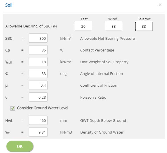 Allowable Dec./Inc. of SBC (%)
↔ Range: -200 to 200 %
Allowable Net Bearing Pressure - SBC↔ Range: 25 to 1000 kN/m2 (0.5 to 20 ksi)
Contact Percentage - Cp↔ Range: 10 to 100 %
Unit Weight of Soil Property - γsoil↔ Range: 10 to 40 kN/m3 (60 to 250 pcf)
Angle of Internal Friction - Φ↔ Range: 0 to 60 deg
Coefficient of Friction - μ↔ Range: 0.05 to 1.5
Poisson's Ratio - ν↔ Range: 0.2 to 1
GWT Depth below Ground - Hwt↔ Range: 0 to 10000 mm (0 to 5000 inches)
Density of Ground Water - γw↔ Range: 5 to 15 kN/m3 (5 to 15 pcf)
Reinforced Concrete Properties (BS 8110)
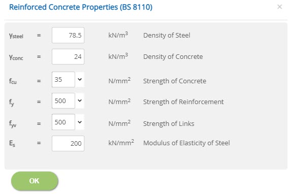 Density of Steel - γsteel
↔ Range: 70 to 80 kN/m3
Density of Concrete - γconc↔ Range: 10 to 40 kN/m3
Strength of Concrete - fcu↔ Range: 15 to 100 N/mm2
Strength of Reinforcement - fy↔ Range: 150 to 2000 N/mm2
Strength of Links - fyv↔ Range: 150 to 2000 N/mm2
Modulus of Elasticity of Steel - Es↔ Range: 50 to 300 kN/mm2
Reinforced Concrete Properties (BS EN 1992-1-1)
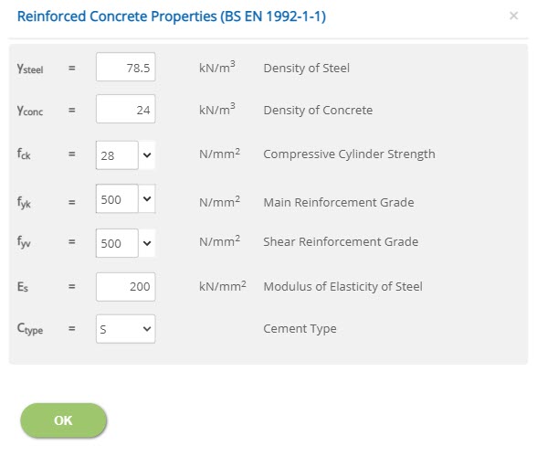 Density of Steel - γsteel
↔ Range: 70 to 80 kN/m3
Density of Concrete - γconc↔ Range: 10 to 40 kN/m3
Compressive Cylinder Strength - fck↔ Range: 15 to 100 N/mm2
Main / Shear Reinforcement Grade - fyk / fyv↔ Range: 150 to 2000 N/mm2
Modulus of Elasticity of Steel - Es↔ Range: 50 to 300 kN/mm2
Cement Type - CtypeSelect the cement type.
Reinforced Concrete Properties (ACI 318M)
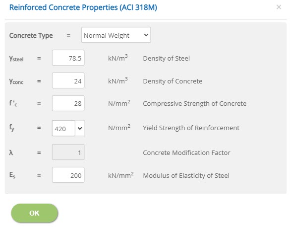 Density of Steel - γsteel
↔ Range: 70 to 80 kN/m3 (450 to 520 pcf)
Density of Concrete - γconc↔ Range: 10 to 40 kN/m3 (60 to 250 pcf)
Compressive Strength of Concrete - f'c↔ Range: 15 to 100 N/mm2 (1 to 15 ksi)
Yield Strength of Reinforcement - fy↔ Range: 150 to 2000 N/mm2 (20 to 300 ksi)
Concrete Modification Factor - λ↔ Range: 0.75 to 1
Modulus of Elasticity of Steel - Es↔ Range: 50 to 300 kN/mm2 (7000 to 45000 ksi)
Material Partial Safety Factors
Enter the material safety factors on selection of British or European Standard and Design Unit from Design Option.
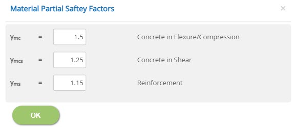
Flexure/Compression / Concrete in Shear / Reinforcement
γmc, γmcs, γms
↔ Range: 1 to 2
Stability Safety Factors
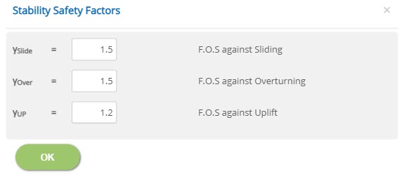 F.O.S against Sliding / Overturning / Uplift
 γslide, γover, γUP
↔ Range: 1 to 5
Crack Width
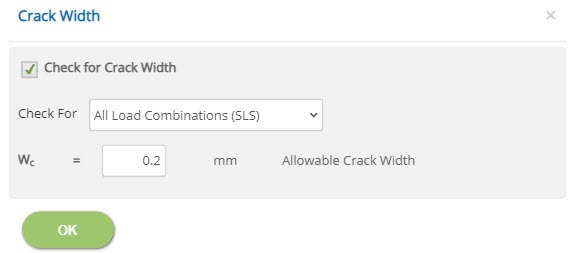
☐ Check for Crack Width: Check this option to consider crack width.
Check For☐ All Load Combinations (SLS): Select this option to check crack width for all load combinations.
☐ Sustained Load Combinations (SLS): Select this option to check crack width for sustained load combinations.
↔ Range: 0.05 to 0.6 mm (0.002 to 0.024 inches)
National Annex
Select the National Annex after selecting the European Standard in Design Option.
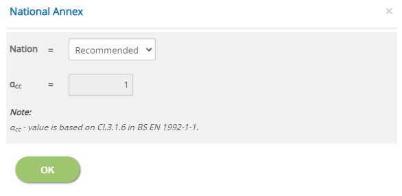
Nation
Select the National Annex option for the relevant factors to be considered in the design.
αcc
Enter the value for the User Defined National Annex option. For other options, this is not editable.
↔ Range: 0.7 to 1.2