> >
Storage Tank Foundation Design
|
|
Download Sample Report |
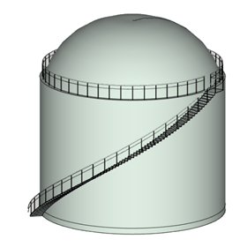
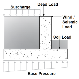
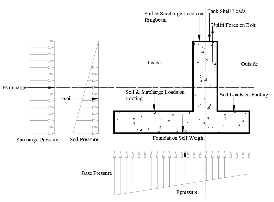
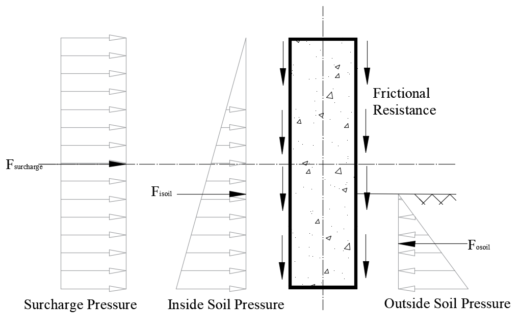
ECTANK application is used to design a storage tank foundation with or without internal pressure for Serviceability (SLS) and Ultimate (ULS) load combinations. Bearing pressure and stability checks are carried out for serviceability loads. Ring beam/wall, footing and grade slab designs are checked for ultimate loads. The sub-structure is designed as a ring foundation with or without footing. The ring beam/wall is designed for hoop tension force created due to soil and surcharge pressures and the torsional moment due to the various load components. The footing is designed to resist the net moment induced due to the tank loads and base pressure. The grade slab is designed to resist the tensile load acting due to membrane action during uplift conditions.
Features
- ECTANK is used to design the following API tank types foundations using API codes requirements. The common types of tank are covered under the following two categories.
- API 650 Tanks (API 650 specification requirements are used for tanks subject to internal pressures up to 18 kN/m2)
- API 620 Tanks (API 620 specification requirements are used for tanks subject to internal pressures greater than 18 kN/m2)
- ECTANK is used to design the following types of tank foundations using above mentioned API codes requirements. The common types of tank foundation are covered under the following categories.
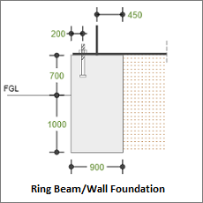
- Ring Beam/Wall Foundation
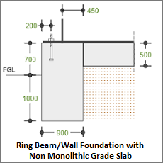
- Ring Beam/Wall Foundation with Non-Monolithic Grade Slab
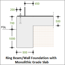
- Ring Beam/Wall Foundation with Monolithic Grade Slab
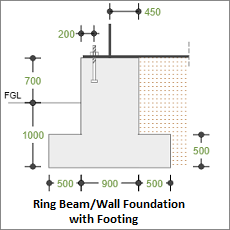
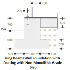
- Ring Beam/Wall Foundation with Footing
- Ring Beam/Wall Foundation with Footing with Non-Monolithic Grade Slab
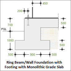
- Ring Beam/Wall Foundation with Footing with Monolithic Grade Slab
- The module gives the user ample amount of choices so as to allow them to model the structure similar to that of actual site conditions such as,
- Roof Type
- Fixed roof - internal pressure cases are considered in the calculation.
- Frangible.
- Non-Frangible.
- Floating roof (external) - internal pressure cases are removed for this roof. type, also the roof loads - roof self-weight, live load and snow loads are considered to be transmitted as surcharge load to the soil.
- Tank loads
- By user / vendor (user input).
- By program (load is computed by the application based on tank details).
- Environmental loads (Wind and Seismic Loads)
- By user / vendor (user input).
- By program (load is computed by the application based on tank details).
- By both (maximum effect of user and program calculated values is considered)
- None (environmental loads such as wind and seismic are not considered in the calculation)
- Load combinations
- User defined – user is permitted to manually define the load factors as per their requirements
- By program – combinations are auto generated. The SLS load combinations are generated as per API-2013 code recommendation which is based on Allowable Stress Load Combinations. The ULS load combinations are auto generated based selected country code in the design options in line with API 650-2013 allowable stress load combinations.
- Seismic Load - By program
- Seismic load effects such as shear, ring beam moment, slab moment (sloshing) and vertical seismic effect coefficients are computed based on API 650-2013 (Annex E) procedure using the site design parameters. In this option the module considers an additional 0.7 factor in the seismic loads, hence in the auto generated load combinations the seismic factors for SLS and ULS are considered as 1 and 1.4 respectively.
- Wind Load - By program
- The user can choose between the following different codes for computing the wind load effects such as wind pressure, shear and moment which enables them to replicate the actual site conditions.
- BS 6399 - using this code involves an effective way of wind pressure calculation based on external pressure coefficients for circular surfaces
- EN 1991.
- ASCE-7 2005
- ASCE-7 2010 - In this option the wind velocity is multiplied by 0.78 as per API recommendations
- ASCE-7 2016 - In this option the wind velocity is multiplied by 0.78 as per
- API recommendations for wind pressure calculation: In this option the wind pressure computed is considered as the uplift pressure acting on the roof and the pressure to shell is calculated by multiplying this value by 0.6 (0.86 /1.44) based on API 650 cl 5.2 (k).
- In addition to the SLS and ULS load combinations, a separate set of critical load combinations recommended by the API code have been predefined in the calculation to check uplift condition and anchorage calculation.
- Provision is available to provide an additional failure pressure can be given by the user which will be included in the above-mentioned critical load combinations for nonfrangible roofs.
- Wind load is calculated automatically by the program based on selection of country code for the design.
- Seismic load calculation is performed automatically by the program based on API 650 Appendix-E.
- Wind and Seismic load calculation are also entered manually based on input by the User or Vendor.
- Wind and Seismic loads can be used by Program simultaneously using by User/Vendor option as well by the Program Option to compare both values and design without any compromise on the quality of input from the Vendors.
- Automatic multiple Load Combination are generated by program based on selection of Design Standard for the design.
- Additional load combinations are also automatically generated by program based on the percentage of increase in empty, operating and test weight. It means that as per user selection of Design Standard, a list of basic load combinations for original loads and one more set of load combinations for the increased loads are generated. Based on this opportunity, the program will define critical load combination without any ambiguity/confusion.
- Ground water table buoyancy effect on stability and design is available for the user to consider as per project requirements.
- For stability check calculations, the user is allowed to give a corrosion allowance so as to reduce the tank empty weight to more accurately capture the site conditions.
- Stability factors (sliding and overturning) and reinforcement adequacy check are carried out for the defined load combinations.
- The user is allowed to specify the nature of earth pressure coefficient used to calculate the lateral pressure forces as either active (ka) or at rest (ko) under soil settings.
- The module also computes the axial tension and moment capacity of the ring beam to resist the hoop tension force and equivalent moment (due to torsion) respectively.
- User can choose to either add or delete snow load effect for the design calculations as per their requirements.
- An option has been provided for the user to either choose standard bolt grades or to define the yield and ultimate strength of bolts which is used for anchorage calculations.
- User can also specify the allowable stability factors and increase or decrease in SBC (Test, Wind and Seismic).
- Loads and Load Combinations can be easily imported from Microsoft Excel through clipboard facility.
- Facility to check the anchorage capacity and interaction ratio for anchor bolts.
- Comprehensive design report and summary results. A step by step design calculation report eliminates any requirements for additional validation of the calculation.
Design Considerations
- Self-weight of soil, ring beam/wall, footing and grade slab is considered by program. Dead Load Factor is used as self-weight factor
- Unfactored loads on foundation system and soil system are calculated based on the SLS combinations.
- Stability factors (overturning, sliding, uplift and SBC) for each load combination are compared with allowable factors (generated by program).
- Pad section crack width is checked for service moment at critical location of pad on two faces (top and bottom) in both directions.
- Moment capacity adequacy is checked for both directions and top and bottom with critical ULS combination.
- One-way shear (Wide Beam Shear) is computed at a distance from ring beam/wall face based on selection of Design Standard. Critical ULS combination and location reported.
- The effect of buoyancy load is considered based on the water table position.
- The calculation module includes wind and seismic load considerations, giving a choice to the user to input the loads directly or to give the general site conditions such as terrain, wind speed, seismic zone, site location etc. And the program gives an accurate load output for the given conditions (subjected to the code provisions)
- In case of coefficient of friction value is given as ‘0’ then sliding check is neglected.
- For sliding check, the loads acting interior to the footing are also considered in the resisting force.
- The load due to grade slab is considered to act as a surcharge on soil similar to that of the product weights.
- The calculation is further proceeded only if the factor of safety for overturning check and uplift check is > 1.
- For anchor bolt calculations, the allowable design stress for tension capacity is taken as per API 650 Table 5.21
- For hoop tension calculations the effect of seismic sloshing pressure is also taken into consideration in applicable cases.
- For uplift critical combination checks in case of non-frangible roofs the frictional resistance acting on the foundation side due to lateral forces is taken into consideration.
- When seismic load calculation is done by program vertical seismic effect is considered to reduce the vertical load in all stability checks. For bearing pressure and twisting moment the seismic effect is considered to either increase or reduce the vertical load so as to consider the effect of the most critical case.
- While calculating torsional moment due to various load components, the centroid of rectangular section (i.e., ring beam portion up to bottom of footing) alone is conservatively considered as opposed to the entire tee section.
National Standards Available
British Standard
Europe Standard
- National Annex of several countries such as Europe (recommended), UK, Finland, Ireland, Malaysia, Norway, Singapore and Sweden are considered.
- Additionally, an option is provided to define the coefficients directly by the user.
American Standard
- The calculation allows the user to design the section both in imperial and metric units.
References
- BS 8110-1:1997 -Structural Use of Concrete - Part 1: Code of practice for design and construction.
- EN1992-1-1:2004 - Design of concrete structures - Part 1-1: General rules and rules for buildings.
- ACI 318-14 - Building Code Requirements for Structural Concrete
- API 650-2013 - Welded Steel Tanks for Oil Storage.
- API 620 - Design and Construction of Large, Welded, Low-Pressure Storage Tanks.
Revision
- Ver 1.0 - Original version
|
|
Download Sample Report |