Help Topics
ECTANK - Storage Tank Foundation Design
ECTANK application is used to design Storage Tank Foundations in the Oil and Gas Industries. This application is mainly used to design foundations for API tanks using very limited available information at any stage of the Project Phases (Proposal or FEED or Detail Engineering or EPC Phases of the Project). ECPlus applications are designed as wizard type which is a step by step guided input procedure. If you are new to ECPlus applications, click here for general guidance to use all EC Plus applications.
ECTANK is used to design the following API tank types foundations using API codes requirements. The common types of tank are covered under the following two categories.
1. API 650 Tanks ( API 650 specification requirements are used for tanks subject to internal pressures up to 18 kN/m2 )
2. API 620 Tanks ( API 620 specification requirements are used for tanks subject to internal pressures greater than 18 kN/m2 )
ECTANK is used to design the following types of tank foundations using above mentioned API codes requirements. The common types of tank foundations are covered under the following categories.
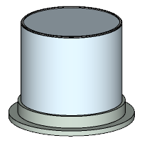
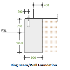
1. Ring Beam/Wall Foundation
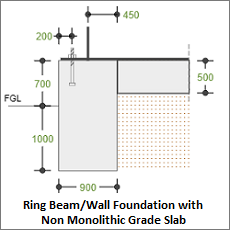
2. Ring Beam/Wall Foundation with Non-Monolithic Grade Slab
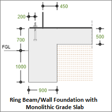
3. Ring Beam/Wall Foundation with Monolithic Grade Slab
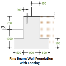
4. Ring Beam/Wall Foundation with Footing
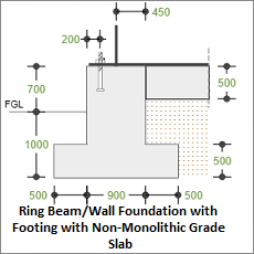
5. Ring Beam/Wall Foundation with Footing with Non-Monolithic Grade Slab
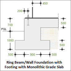
6. Ring Beam/Wall Foundation with Footing with Monolithic Grade Slab
Prerequisites: The user is expected to have a basic understanding of tank foundation design concepts. However, this software tool is very user friendly even for civil engineering graduate trainees.
The minimum input data required to use this application are as follows:
- ❶ Soil data such as Safe Bearing Capacity, Density of Soil, Angle of Internal Friction, Co- efficient of internal friction between bottom of foundation / soil, Ground Water Table and other soil parameters, reinforced concrete properties, Allowable Stability Safety Factors, etc., which are to be defined in the settings by the User
- ❷ Design Options
- ❸ Equipment Geometric Data
- ❹ Ring Beam, Footing and Grade Slab information as applicable to user requirements
- ❺ Design parameters for Environmental design loads of such as wind and seismic as per country code requirements
Design Options
This page allows the user to select the foundation support system, i.e. soil or pile, tank type, design standard and unit.
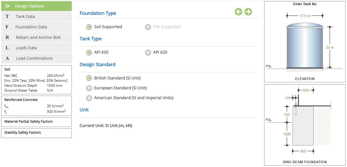
Foundation Type
Select if the foundation is supported on Soil or Pile.
The user-friendly radio button option is selected by the user according to the foundation type. The application is having option to select the foundation type as on Soil Supported or Pile- Supported. Presently, only soil supported option is available. Based on selection, the input field as applicable to the foundation type is enabled for the user to exercise information as required to design the foundation.
Pile option is not available in the current version.
Tank Type
Select if the tank type is API 650 or API 620
☉API 650 specification requirements are used for tanks subject to internal pressures up to 18 kN/m2
☉API 620 specification requirements are used for tanks subject to internal pressures greater than 18 kN/m2
Design Standard
Select the National Standard for the design. Available Standards: ☉British, ☉European and ☉American.
Unit
It displays the active unit. The unit Change button is displayed when ☉American Standard is selected.
British and European Standards can not be selected when Imperial unit is active.
Change
Click this button to open the unit change pop-up dialog.
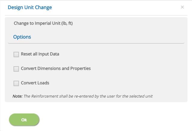
☐ Reset all Input Data
This option will reset the input data from the current unit to change (new) unit under American Standard option. This option is recommended if the job is new and no input data has been entered yet.
☐ Convert Dimensions and Properties
This option allows to convert all the previously entered input data except Load data to the new unit.
☐ Convert Loads
This option allows to convert previously entered load data to the new unit.
Note: Both Convert Dimensions and Properties and Convert Loads options can be used simultaneously to convert all the previously entered input values to the new unit.
- Note: While the program attempts to reasonably convert the rebar sizes equivalent to the new unit, the user should verify the reinforcement pages of pad and pedestal to ensure that the conversion has been applied as expected.
Incorrect option leads to out of range errors and should be manually corrected.
- Note: What is the meaning of a Range used in the user manual? Range is a predefined limit set in the application to ensure user to enter values within these limits by providing a warning to the user. This will avoid user to enter any illogical values by mistake which may crash the program or abrupt end of the calculation. In case user wants to change these limits, the same may be communicated to EC PLUS Technical Support Team using Contact Us.
Tank Data
This page allows the input of tank data such as roof type, tank diameter, shell height, roof height, bolt centre diameter, corrosion allowance and internal pressure. All these input parameters shall be available in Mechanical Data Sheet or Vendor Drawings.
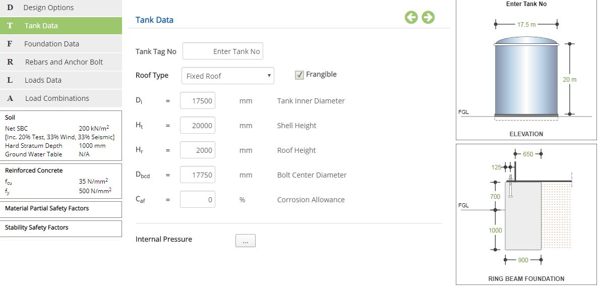
Tank Tag No
Enter the tag number for the tank based on input.
Roof Type
Select the type of roof from the drop-down menu.
▽ Fixed Roof: Select this option to use fixed roof tank. Internal pressure input menu is enabled in case of fixed type roof. The fixed roof type tanks may be with or without internal floating roof. This is only differentiated in the load input data by providing internal floating roof weight if applicable. In the absence of floating roof and dome type tanks, the internal floating roof weight will be zero.
☐ Frangible (Applicable for Fixed Roofs alone): Use this option to consider the roof as a Frangible or Non Frangible based on types of roof design. For Non Frangible roofs additional Failure Pressure check is considered as per API code requirements and the foundation is also checked for the critical load combinations as per clause 5.10.2.6(d) of API 650-2013.
▽ Floating Roof (External): Select this option to use floating roof tank. Internal pressure input menu option is not displayed in case of floating roof type. The purpose of the floating roof is to avoid internal pressure inside the tank. This type of roof will automatically reduce the requirement of heavy foundation system for uplift requirements. However, the cost of internal roof and maintenance requirements may be higher than external floating roof.
Tank Inner Diameter - Di
Enter the inner diameter of the tank (Di) as per input.
↔ Range: >= 2000 mm (>= 75 inches)
Shell Height - Ht
Enter the height of the tank shell (Ht) as per input.
↔ Range: >= 2000 mm (>= 80 inches)
Roof Height - Hr
Enter the height of the roof (Hr) as per input.
↔ Range: 0 to 10000 mm (0 to 500 inches)
Bolt Center Diameter - Dbcd
Enter the bolt center diameter (Dbcd) as per input.
↔ Range: >= 2000 mm (>= 75 inches)
Corrosion Allowance - Caf
Enter the corrosion allowance factor (Caf) in % for the tank based on input. Normally, this input is in “mm” or “inches” based on unit used in the project which is to be converted as a percentage (%) with respect to original thickness of base plate / shell / roof elements. In case of varying thickness, approximately an average thickness may be considered.
Corrosion Allowance Factor (Caf) = {(Original Thickness – Corrosion Allowance) / (Original Thickness)} x 100.
↔ Range: 0 to 90 %
Internal Pressure
Click this button to open the internal pressure pop-up dialog. The internal design pressure shall be based on code requirements which shall be decided by the customer based on operating pressure.
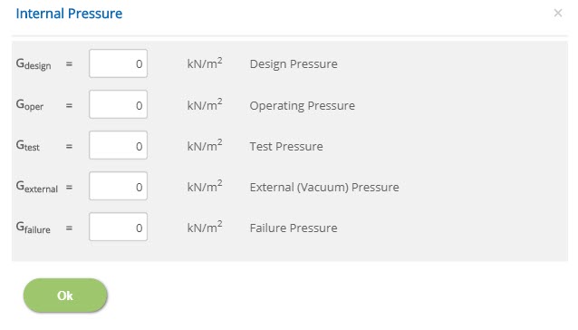
Design Pressure - Gdesign
Enter the design pressure (Gdesign) as per input.
↔ Range: 0 to 100 kN/m2 (0 to 2 ksf)
Operating Pressure - Goper
Enter the operating pressure (Goper) as per input.
↔ Range: 0 to 100 kN/m2 (0 to 2 ksf)
Test Pressure - Gtest
Enter the test pressure (Gtest) as per input.
↔ Range: 0 to 125 kN/m2 (0 to 2.6 ksf)
As per API 620 - 7.18.3.2 and 7.18.4.2, the test pressure shall be 1.25 times the design internal pressure.
External (Vacuum) Pressure - Gexternal
Enter the external pressure (Gexternal) as per input. The external vacuum pressure reduces the uplift and increases the bearing pressure.
↔ Range: 0 to 6.9 kN/m2 (0 to 0.15 ksf)
As per API 650-2013 clause 5.21(b), the external pressure shall not be less than 0.25 kPa for tanks without circulation vents. For values higher than 0.25 kPa Annex V shall be referred.
Failure Pressure (Applicable for Non Frangible Fixed Roofs) - Gfailure
Enter the failure pressure (Gfailure) as per input.
↔ Range: 0 to 300 kN/m2 (0 to 6 ksf)
The Failure Pressure shall be computed as per clause F.7 of API 650-2013.
Foundation Data
This page allows the user to provide input for foundation data such as depth of foundation (Df), height of ring beam above ground (Hag), width of ring beam (Ww), width of ring beam contact with fluid (Wwf), grade slab and footing details.
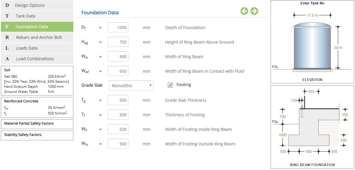
Depth of Foundation - Df
Enter the depth of the foundation (Df) as per input.
↔ Range: 300 to 6000 mm (12 to 240 in)
As per API 650 - B4.2.2, The minimum ring beam depth shall be 600 mm (24 in).
Height of Ring Beam Above Ground - Hag
Enter the height of ring beam above ground (Hag) as per input.
↔ Range: 0 to 6000 mm (0 to 240 in)
As per API 650 - B.3.1, the minimum Height above grade shall be 300 mm (12 in). In case of large Settlement the same shall be 150 mm (6 in) after Settlement.
Width of Ring Beam - Ww
Enter the width of the ring beam (Ww) as per input.
↔ Range: 200 to 10000 mm (8 to 75 in)
As per API650-B.4.2.2, the minimum width of ring beam shall be of 300mm.
Width of Ring Beam in Contact with Fluid - Wwf
Enter the width of the ring beam in contact with the fluid (Wwf) as per input. This is the distance between edge of the ring beam inside to the inside diameter of the tank.
↔ Range: 50 to 2000 mm (2 to 75 in)
Grade Slab
▽ Monolithic: Select this option to use monolithic grade slab. The monolithic grade slab facility is useful to perform analysis of tank foundation with internal pressure. The combined system (tank bottom base plate + monolithic grade slab) acts like a rigid system which will resist the internal pressure. Hence, the same module may also be used for any structural supported tank bottom plate which is also a rigid system to resist the internal pressure.
▽ Non - Monolithic: Select this option to use non-monolithic grade slab. The non monolithic grade slab is just provided to protect tank bottom plate from the corrosion. Otherwise, the design of storage tank foundation system is as similar to without grade slab. The behaviour of the tank bottom plate is flexible in nature which will not resist any internal pressure. Hence, the entire uplift loads are to be counterbalanced by the foundation system.
▽ None: Select this option to design tank without grade slab. The behaviour of the tank bottom plate shall be flexible in nature which will not resist any internal pressure. Hence, the entire uplift loads shall be counterbalanced by the foundation system.
☐ Footing: Check this option to provide ring beam foundation with footing.
As per API 650 B.4.2, if the ring beam width exceeds 460 mm (18 in), Footing shall be recommended.
Grade Slab Thickness - Tg
Enter the thickness of the grade slab (Tg) as per input.
↔ Range: 50 to 2000 mm (2 to 75 in)
Thickness of Footing - Tf
Enter the thickness of the footing (Tf) as per input.
↔ Range: 300 to 5000 mm (12 to 200 in)
Width of Footing Inside Ring Beam - Wfi
Enter the width of the footing inside the ring beam (Wfi) as per input.
↔ Range: 0 to 5000 mm (0 to 200 in)
Width of Footing Outside Ring Beam - Wfo
Enter the width of the footing outside the ring beam (Wfo) as per input.
↔ Range: 0 to 5000 mm (0 to 200 in)
- Note: For Design, the weight of Grade slab is considered to be transferred as a surcharge pressure through the soil similar to that of tank content loads.
- Note: Grade Slab is considered mainly for analysis purpose. For design purpose the tension resistance of the grade slab is computed which is checked against the Tension force caused by slab due to pressure from settlement. For more detailed design User is advised to use FEM.
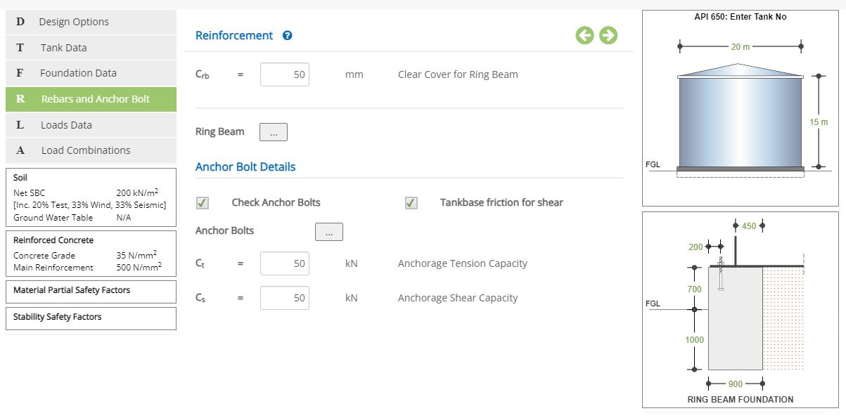
Rebars and Anchor Bolt
This page allows the user to enter reinforcement and anchor bolt details.
Clear Cover for Footing - Cfoot
Enter clear cover for footing (Cfoot) reinforcements as per input.
↔ Range: 15 to 150 mm (0.5 to 6 in)
Clear Cover for Ring Beam - Crb
Enter clear cover for ring beam (Crb) reinforcements as per input.
↔ Range: 15 to 150 mm (0.5 to 6 in)
Clear Cover for Grade Slab - Cgs
Enter clear cover for grade slab (Cgs) reinforcements as per input.
↔ Range: 15 to 150 mm (0.5 to 6 in)
☐ Check Anchor Bolts: Check this option to include anchor bolts check.
☐ Tankbase Friction for Shear: Check this option if shear force is to be resisted by tank base friction.
As per API 650 shear force is resisted by tank base friction.
Anchorage Tension Capacity - Ct
Enter the anchorage tension capacity (Ct) for bolt system.
↔ Range: 0 to 5000 kN (0 to 1125 kips)
Anchorage Shear Capacity - Cs
Enter the anchorage shear capacity (Cs) for bolt system.
↔ Range: 0 to 5000 kN (0 to 1125 kips)
- Note: For anchor bolt calculations, the allowable design stress for tension capacity is taken as per API 650 Table 5.21 as follows,
1. Operating condition - 0.45 * tensile stress of bolt.
2. Test case - 0.6 * tensile stress of bolt.
3. Wind condition - 0.8 * tensile stress of bolt.
4. Seismic condition - 0.8 * tensile stress of bolt.
5. Seismic + Operating condition - 0.8 * tensile stress of bolt.
6. Wind + Operating condition - 0.6 * tensile stress of bolt.
7. Wind + Test condition - 0.6 * tensile stress of bolt.
8. Failure pressure condition - 1 * tensile stress of bolts.
Ring Beam
Click this button to open the reinforcement for ring beam pop-up dialog.
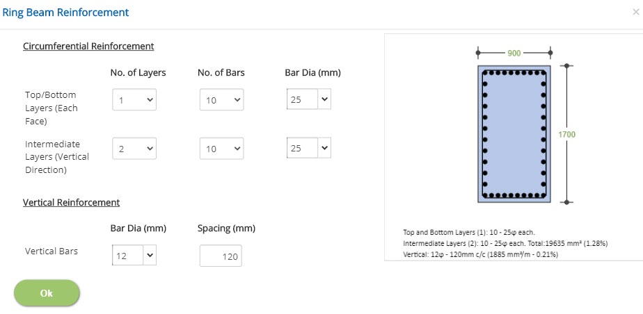
No. of Layers
Select the number of layers for top/bottom and intermediate layers. The top and bottom layers are in horizontal direction and maximum 2 layers can be provided. The intermediate layers are in vertical direction and maximum 4 layers can be selected.
No. of Bars
Select the number of bars for top/bottom and intermediate layers.
Bar Dia
Select the bar diameter for top/bottom, intermediate layers and vertical reinforcement.
↔ Range: 4 to 60 mm
Spacing
Enter the spacing of the vertical reinforcement.
↔ Range: 20 to 450 mm (1 to 18 inches)
Footing
Click this button to open the reinforcement for footing pop-up dialog to provide reinforcements input in main and circumferential directions at top and bottom of the footing. The reinforcement diameter and spacing are supplied as input which is validated by the program against actual capacity with required capacity. The total area of the reinforcements with percentage (%) in each direction is shown below the reinforcement diagram for user quick reference. This is useful for the user to take any decision to modify already provided data for reinforcements. In the case of the footing, the bottom/top reinforcements in the main (radial) direction is for tension reinforcements which are to be satisfied for the minimum % tension reinforcement to the selected country code. The circumferential secondary reinforcements are to be satisfied for the minimum % of temperature reinforcement to the selected country code. However, the user has option to provide input based on analysis results, engineering judgement to satisfy code requirements.
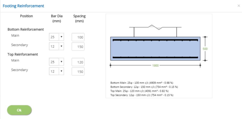
Bar Dia (mm or # No.)
Select the bar diameter for bottom and top reinforcement.
↔ Range: 4 to 60 mm (2 to 18 # No.)
Spacing (mm or in)
Enter the spacing for bottom and top reinforcement.
↔ Range: 20 to 450 mm (1 to 18 inches)
Grade Slab
Click this button to open the reinforcement for grade slab pop-up dialog.
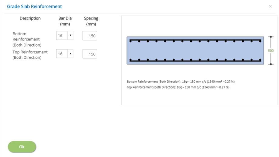
Bar Dia (mm or # No.)
Select the bar diameter for bottom and top reinforcement.
↔ Range: 4 to 60 mm (2 to 18 # No.)
Spacing (mm or in)
Enter the spacing for bottom and top reinforcement.
↔ Range: 20 to 450 mm (1 to 18 inches)
Anchor Bolts
Click this button to open the anchor bolts pop-up dialog.
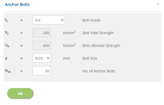
Bolt Grade - fb
Select the bolt grade (fb) as per input.
Bolt Yield Strength - Yb
The default bolt material yield strength (Yb) is displayed as per selected grade. In case of user defined grade, this input field is enabled to enter bolt yield strength by the user.
↔ Range: 100 to 1000 N/mm2 (15 to 145 ksi)
Bolt Ultimate Strength - Ub
The default bolt material ultimate strength (Ub) is displayed as per selected grade. In case of user defined grade, this input field is enabled to enter bolt ultimate strength by the user.
↔ Range: 100 to 1000 N/mm2 (15 to 145 ksi)
Bolt Size - d
Select the bolt size (d) as per input.
No. of Anchor Bolts - Nab
Enter the number of anchor bolts (Nab) in the circumferential direction as per input.
↔ Range: 1 to 100
Loads Data
This page allows user to enter load data for wind, seismic and tank loads. The wind and seismic loads are entered based on options (By User / Vendor, By Program, By Both or None) as per user choice. In addition, the user options are not limited to select any one country code or any one option. Example, the wind loads may be entered By User/Vendor option and at the same time the seismic load may be generated By Program or By Both options.
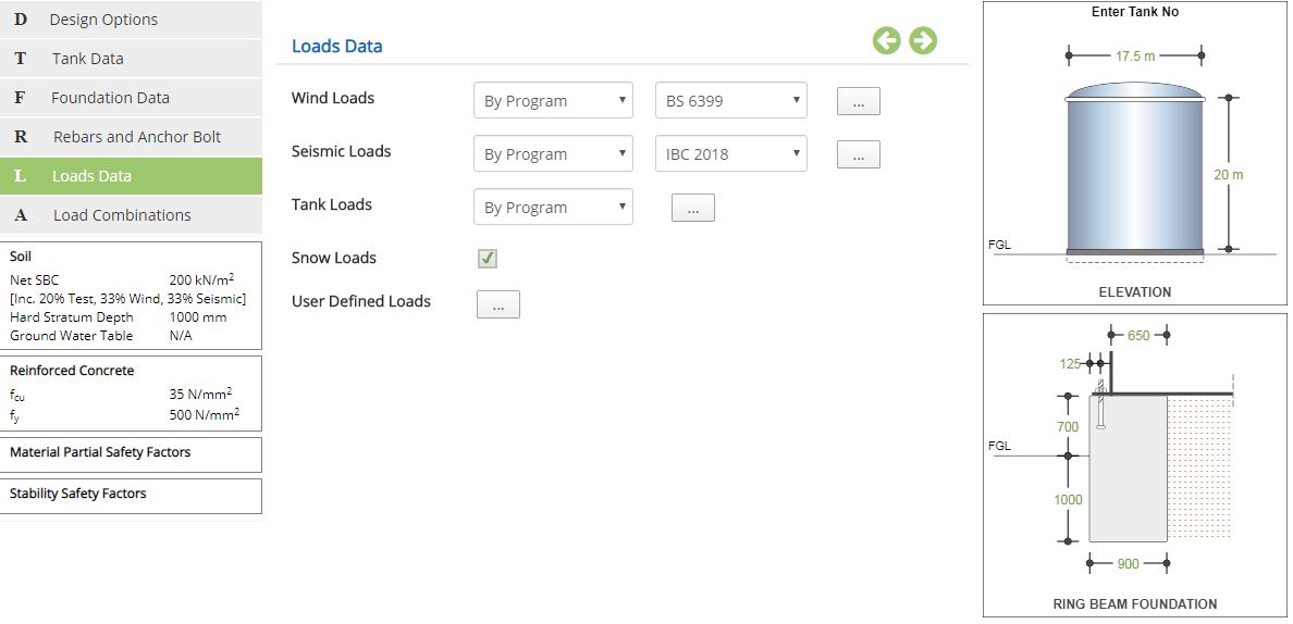 Wind / Seismic Loads
▽ By User / Vendor: Select this option to use wind / seismic loads By User / Vendor. If the information is readily available with user from vendor or any other source, the User/Vendor option is selected. In this case, the actual wind/seismic loads are to be entered under Tank Loads as applicable.
▽ By Program: Select this option to calculate wind/seismic loads automatically by the program. The required parameters to calculate automatically by the program are to be entered as per selected country code. Please note that the wind / seismic loads are automatically calculated by the program based on provided parameter input for the selected country code.
▽ By Both: Select this option to use loads by both user / vendor and program. In this option, the user is provided with both options to enter input. The program calculated automatic shear / moment values are compared with user/vendor shear and moment values input. The maximum values are conservatively used for the calculation. However, based on comparison of user input and program calculated values, the user may take any appropriate decision either to proceed or comment any discrepancies to the vendor or inter-disciplines (source of input) to clarify / rectify before implementation.
▽ None: Select this option not to consider selected loads.
▽ Code: Select the appropriate country code to use in case of by program or by both options to calculate wind and seismic loads.
Wind Load by Program - BS 6399
Click this button to open the wind load by program popup based on British Standard BS 6399.
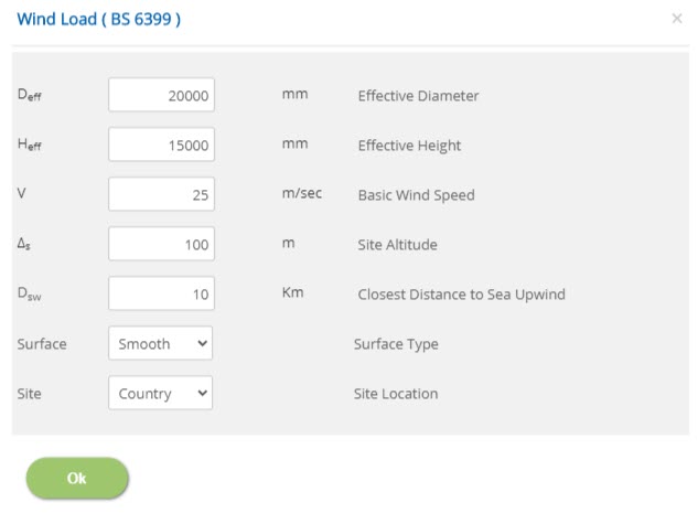 Effective Diameter - Deff
Enter the effective diameter (Deff), which includes shell thickness, insulation, extra fittings etc., to account for wind exposed area calculation in a perpendicular to wind direction. As a minimum, the effective diameter shall equal to diameter of tank. Hence, this is cross validated by the program and warning/error is produced to the user for an appropriate action.
↔ Range: >= 0 mm (>= 0 inches)
Enter the effective height (Heff), which includes shell thickness, insulation, extra fittings etc., to account for wind exposed area calculation in the perpendicular wind direction. As a minimum, the effective height shall equal to height of tank. Hence, this is cross validated by the program and warning/error is produced to the user for an appropriate action.
↔ Range: >= 0 mm (>= 0 inches)
Enter the basic wind speed (V), as per design criteria as applicable to the country code. This value shall be carefully decided by the user based on customer input as applicable to the selected country code to avoid any mistake.
↔ Range: 10 to 500 m/s (30 to 1700 ft/sec)
Enter the site altitude (Δs) based on available information with reference to Mean Sea Level (MSL).
↔ Range: 10 to 500 m (30 to 1700 inches)
Closest Distance to Sea Upwind - Dsw
Enter the closest distance to sea upwind (Dsw) based on available input.
↔ Range: 10 to 1000 km (6 to 700 Mile)
Select the surface type. The available options are Smooth and Rough surfaces.
Site LocationSelect the site location. The available options are Country and Town.
Wind Load by Program - EN 1991
Click this button to open the wind load by program popup based on Euro Standard BS EN 1991.
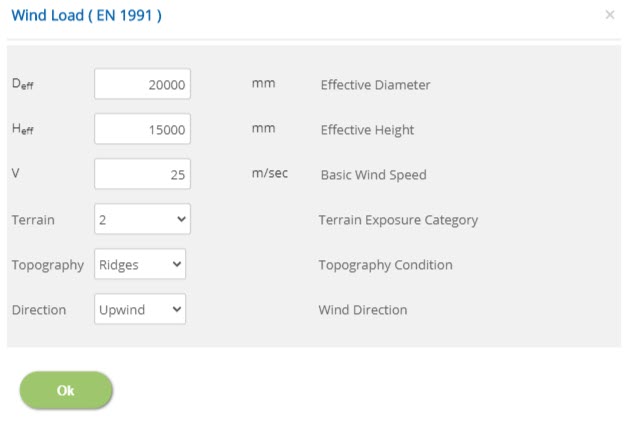 Effective Diameter - Deff
Enter the effective diameter (Deff), which includes shell thickness, insulation, extra fittings etc., to account for wind exposed area calculation in a perpendicular wind direction. As a minimum, the effective diameter shall equal to diameter of tank. Hence, this is cross validated by the program and warning/error is produced to the user for an appropriate action.
↔ Range: >= 0 mm ( >=0 inches)
Enter the effective height (Heff), which includes shell thickness, insulation, extra fittings etc., to account for wind exposed area calculation in the perpendicular wind direction. As a minimum, the effective height shall equal to height of tank. Hence, this is cross validated by the program and warning/error is produced to the user for an appropriate action.
↔ Range: >= 0 mm ( >=0 inches)
Enter the basic wind speed (V), as per design criteria as applicable to the country code. This value shall be carefully decided by the user based on customer input as applicable to the selected country code to avoid any mistake.
↔ Range: 10 to 500 m/s (30 to 1700 ft/sec)
Select the terrain exposure category. The available options are 0, 1, 2, 3 & 4.
Topography ConditionSelect the topography condition. The available options are Ridges, Escarpments, Hill & Cliff.
Wind DirectionSelect the wind direction. The available options are up wind and down wind.
Wind Load by Program - ASCE-7
Click this button to open the wind load by program popup based on ASCE 7 - 2005, 2010 & 2016.
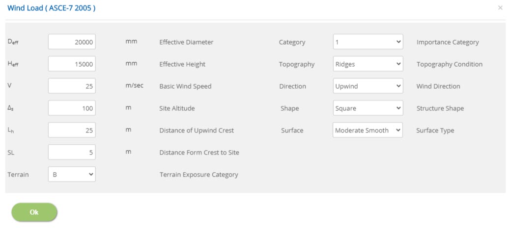 Effective Diameter - Deff
Enter the effective diameter (Deff), which includes shell thickness, insulation, extra fittings etc., to account for wind exposed area calculation in a perpendicular to wind direction. As a minimum, the effective diameter shall equal to diameter of tank. Hence, this is cross validated by the program and warning/error is produced to the user for an appropriate action.
↔ Range: 200 to 10000 mm (8 to 400 inches)
Enter the effective height (Heff), which includes shell thickness, insulation, extra fittings etc., to account for wind exposed area calculation in the perpendicular wind direction. As a minimum, the effective height shall equal to height of tank. Hence, this is cross validated by the program and warning/error is produced to the user for an appropriate action.
↔ Range: 100 to 2000 mm (4 to 80 inches)
Enter the basic wind speed (V), as per design criteria as applicable to the country code. This value shall be carefully decided by the user based on customer input as applicable to the selected country code to avoid any mistake.
↔ Range: 10 to 500 m/s (30 to 1700 ft/s)
Enter the site altitude (Δs) based on available information with reference to Mean Sea Level (MSL).
↔ Range: 10 to 500 m (30 to 1700 ft)
Enter the distance of upwind crest (Lh) as applicable.
↔ Range: 10 to 500 m (30 to 1700 ft)
Enter the distance from crest to site (SL) as applicable.
↔ Range: 1 to 500 m (3 to 1700 ft)
Select the terrain exposure category. The available options are B, C & D.
Importance CategorySelect the importance category. The available options are 0, 1, 2, 3 & 4.
Topography ConditionSelect the topography condition. The available options are Ridges, Escarpments, Hill & Cliff.
Wind DirectionSelect the wind direction. The available options are up wind and down wind.
Structure ShapeSelect the shape of the structure.
Surface TypeEnter the type of the surface. The available options are Moderate Smooth, Rough and Very Rough Surfaces.
Seismic Load by Program - API 650 2013
Click this button to open the seismic load by program popup based on API 650 2013. The other codes like ASCE-7 – 2005, 2010, 2016, IBC 2018, etc., are not having provision specific to Storage Tanks. Hence, seismic load calculation using these referred codes are not provided in the option except API 650 2013 which mainly deals with Storage Tanks.
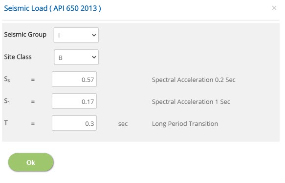 Seismic Group
Select the seismic group. The available options are I, II & III.
Site ClassSelect the site class. The available options are A, B, C, D, E & F.
Spectral Acceleration 0.2 Sec - SsEnter the spectral acceleration at 0.2 second.
↔ Range: 0.2 to 10
Enter the spectral acceleration at 1 second.
↔ Range: 0.2 to 10
Enter the spectral acceleration for long period.
↔ Range: 0.1 to 5
▽ By User / Vendor: Select this option to use loads by user / vendor under User Defined Loads. Based on selection, the user defined input fields are in editable mode to receive input from user. Accordingly, enter axial load, shear and moment at tank base for empty weight, tank bottom plate weight, floating roof weight, operating weight, test weight, live load, snow load, wind load, seismic load for ring beam and slab component. The availability of wind / seismic loads are based on selection of menu option under Loads Data under Wind and Seismic.
▽ By Program: Select this option to use loads by program. In this option, the following listed loads, the Tank Empty Weight (De), Tank Bottom Plate Weight (Dbp), Floating Roof Weight (Drs), Operating Weight (Do) and Test Weight (Dt) are automatically calculated by program based on user input. Hence, input for these fields are not editable under user defined loads.
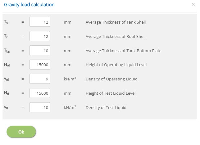 Average Thickness of Tank Shell
Enter the average thickness of tank shell.
↔ Range: 0 to 100 mm (0 to 4 inches)
Enter the average thickness of roof shell.
↔ Range: 0 to 100 mm (0 to 4 inches)
Enter the average thickness of the bottom plate of tank.
↔ Range: 0 to 100 mm (0 to 4 inches)
Enter the height of the operating liquid level.
↔ Range: >= 2000 mm (>= 80 inches)
Enter the density of operating liquid.
↔ Range: 1 to 20 kN/m3 (5 to 130 pcf)
Enter the height of the test liquid level.
↔ Range: >= 2000 mm (>= 80 inches)
Enter the density of test liquid.
↔ Range: 1 to 20 kN/m3 (5 to 130 pcf)
☐ Snow Loads: Check this option to consider any loads due to snow on the tank. This check box facility is kept outside before to enter tank load menu option in order to receive an input if applicable. If it is unchecked, the same shall not be editable by the user.
User Defined Loads
Click this button to open the load cases / load data pop-up dialog to provide user defined tank loads to enter input for all vertical gravity loads and associated shear forces/moments. The appearance of user input field will vary based on selection of menu option (By User / Vendor or By Program) under tank loads.
User Defined Loads: (Wind, Seismic, Tank loads By User / Vendor):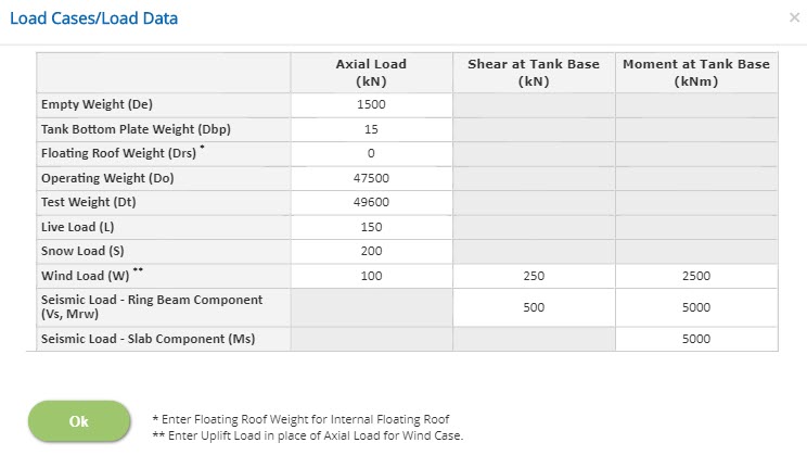 User Defined Loads: (Wind, Seismic, Tank loads By Program):
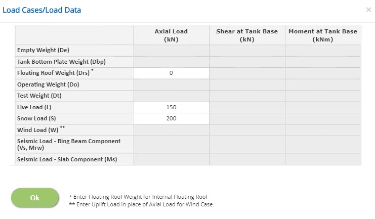 User Defined Loads: (Wind, Seismic loads By User / Vendor, Tank loads By Program):
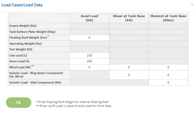
Enter axial load, shear and moment at tank base for empty weight, tank bottom plate weight, floating roof weight, operating weight, test weight, live load, snow load, wind load, seismic load for ring beam and slab component.
Empty Weight - De
Enter the empty weight of the tank (De) as per user input selection as applicable.
↔ Range: -100000 to 100000
Operating Weight - Do
Enter the operating weight for the tank (Do) as per user input selection as applicable.
↔ Range: -100000 to 100000
Test Weight - Dt
Enter the test weight for the tank (Dt) as per user input selection as applicable.
↔ Range: -100000 to 100000
Live Load - L
Enter the live load (L) on the tank roof top mounted platform as per input. In the absence of information, the recommended live loads as per PIP for access platforms is 2.87kN/m2 (60psf) and for operating platforms is 4.79kN/m2 (100psf) unless otherwise specified.
↔ Range: -100000 to 100000
Live Load Intensity x Area of the platform shall be entered in this row. The uniform area load is multiplied with effective platform area to apply as a concentrated load to enter against the input field Axial load.
Snow Load
Enter the snow load (S) on the tank roof top mounted platform as per input.
Snow Load Intensity * Area of the platform shall be entered in this row.
The uniform area load is multiplied with effective platform area to apply as a concentrated load to enter against the input field Axial load.
↔ Range: -100000 to 100000
Wind Load - W
This wind load input field is enabled when the user selects wind load by vendor/user or by both. Enter the wind load as per input. The anchor bolt connection between tank shell and ring beam/wall is considered as fixed to resist wind shear and moments.
The wind pressure on tank shell is applied as a shear force and moments at tank base. The wind pressure on roof is applied as an uplift load as per API 650.
Seismic Load - Ring Beam Component - (Vs & Mrw)
Enter the seismic load for ring beam / wall component as a shear force (Vs) and ring moment (Mrw).
As per API 650-2013 Annex E, the ring beam / wall moment is the portion of the total overturning moment that acts at the base of the tank shell perimeter. This moment is used to determine loads on a ring beam/wall foundation, the tank anchorage forces.
Seismic Load - Slab Component - Ms
Enter the seismic load for slab component.
↔ Range: -100000 to 100000
As per API 650-2013 Annex E, the slab moment is the total overturning moment acting across the entire tank base cross-section. This overturning moment is used to design grade slab.
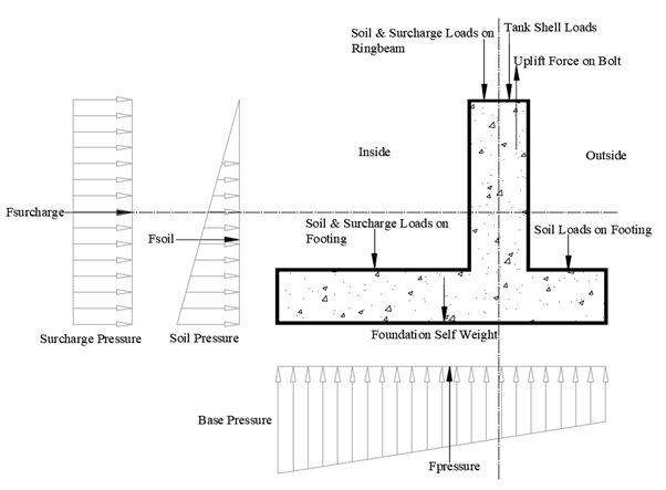
- Note: Load Distribution: The Tank Empty Load along with roof loads (Snow, Live & Roof Weight) in case of Fixed roof is transferred as Shell Edge load to the Ring Beam. The Content Loads are split as components acting partially on ring beam, footing and remaining as surcharge on soil. In case of Floating Roof the roof loads (Snow, Live & Roof Weight) acts similarly. Internal Pressure Forces act as both tension (uplift force) and Compression on the foundation. The net resultant of these two forces is used for design and analysis. In case of External Vacuum Pressure, only compression force prevails.
Load Combinations
This page allows the user to select load combinations as per applicable country code.
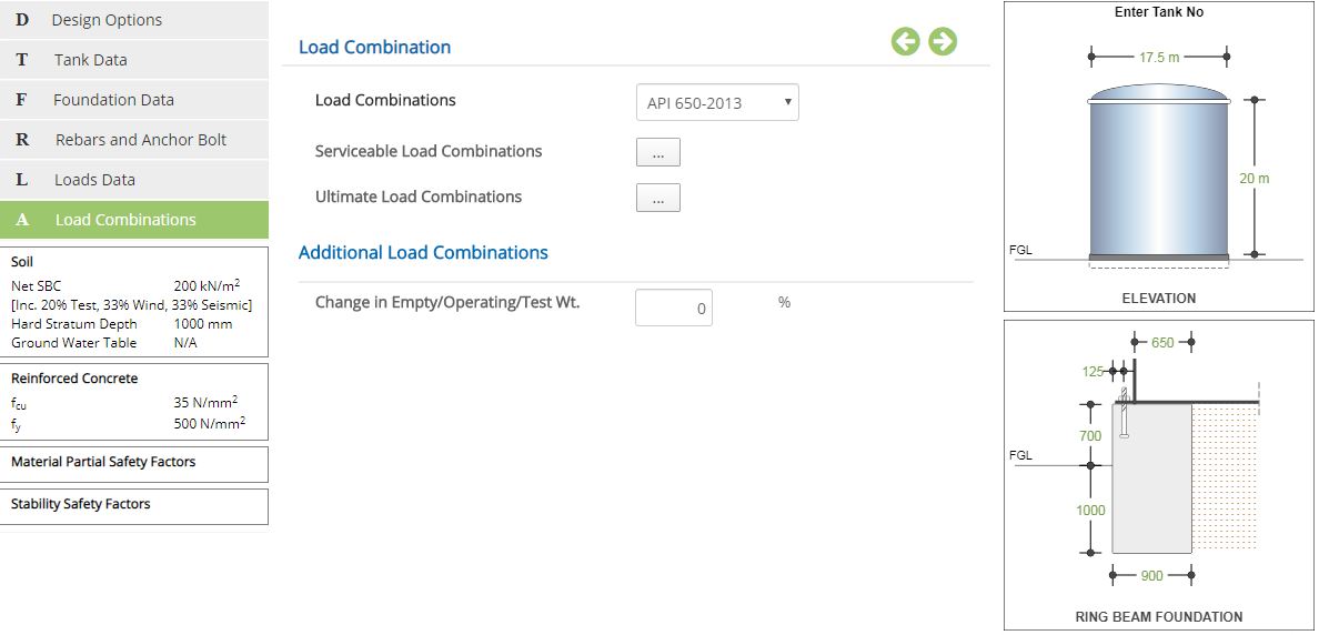
Load Combinations
Select the country code to apply applicable load combinations automatically. As the ECTANK design is based on API 650/620 specifications, the load combination is also followed as per API 650 load combinations. Hence, no other country code provision is required and is not provided for the user. Alternatively, user-defined option is selected to enter load combinations manually, as per preference of the user. In this case, a default load combination as per API 650 is displayed for user convenience and the same load combinations can be easily edited by the user as per requirements.
The code applicable for auto combination is API 650 - 2013
Service Load Combinations
Click this button to open the pop-up dialog to define the service load combinations. This is a spreadsheet type input dialog - right click on the spreadsheet to add or delete rows. Alternatively, the user can copy and paste data from an external source such as Microsoft Excel.
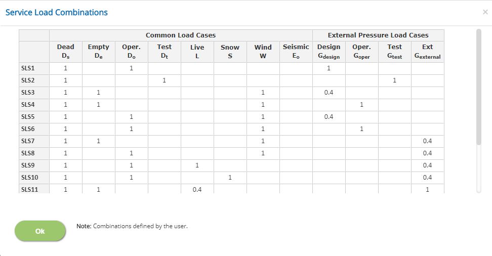
Displays the service load combinations as per the country code selected.
In case of different service load combination is required, the user-defined option is to be selected to create new service load combination as required by the user.
↔ Range: -10 to 10
- Note: For Dead Load case type, which is the first column, the factor should be a positive non-zero value.
Ultimate Load Combinations
Click this button to open the pop-up dialog to define the ultimate load combinations. This is a spreadsheet type input dialog - right click on the spreadsheet to add or delete rows. Alternatively, the user can copy and paste data from an external source such as Microsoft Excel.
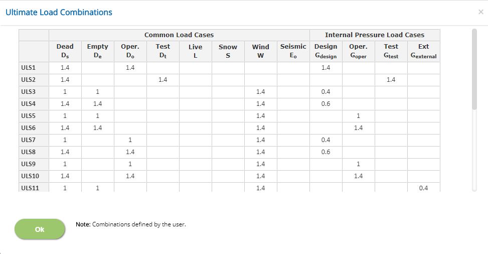
Displays the ultimate load combinations as per the country code selected.
In case of different ultimate load combination is required, the user-defined option is to be selected to create new ultimate load combination as required by the user.
↔ Range: -20 to 20
- Note: For Dead Load case type, which is the first column, the factor should be a positive non-zero value.
Additional Load Combinations
Change in Empty/ Operating/ Test Wt.
Enter the percentage of change in empty / operating and test weights to add additional load combinations. The default value of “zero” will ensure that no more additional combinations are added for checking. In case of non-zero values, additional load combinations are also added as like original load combinations to design the foundation based on increased load weights.
↔ Range: 0 to 100 %
- Note: Based on the change in empty / operational / additional / test weight, SLS and ULS combinations will be created for the calculation in the back end of the program automatically. This unique facility helps to detect the critical load combination automatically by the ECTANK for the present loads as well as increased loads.
Design Setting
Setting for various Design Data such as Soil, Concrete, Passive Resistance and Material and Safety Factors are presented in this section. This setting pop-up can be accessed by clicking the bottom panel below the left navigation.
Soil
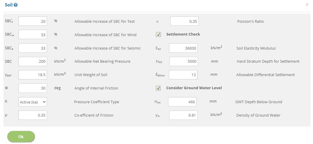
Allowable Increase of SBC for Test / Wind / Seismic
SBCt, SBCw, SBCs
↔ Range: 0 to 100 %
Allowable Net Bearing Pressure - SBC
↔ Range: 25 to 1000 kN/m2 (0.5 to 20 ksf)
Unit Weight of Soil - γsoil
↔ Range: 10 to 40 kN/m3 (60 to 250 pcf)
Angle of Internal Friction - Φ
↔ Range: 0 to 60 deg
Pressure Coefficient Type - K
Select the type of pressure coefficient.
Co-efficient of Friction - μ
↔ Range: 0 to 1.5
Poisson's Ratio - v
↔ Range: 0.1 to 1
☐ Settlement Check: Check this option to enable settlement check. Settlement check will be available, when Grade slab is selected as Non - Monolithic or None in Foundation Data. In case of, Monolithic grade slab, settlement check will be considered by default.
Soil Elasticity Modulus - Eso
↔ Range: 350 to 320000 kN/m2 (7 to 7000 ksf)
Hard Stratum Depth for Settlement - Hsd
↔ Range: >= 0 mm (>= 0 inches)
Allowable Differential Settlement - δallow
↔ Range: 10 to 50 mm (0.3 to 2 inches)
☐ Consider Ground Water Level: Enable this option to consider ground water level.
GWT Depth Below Ground - Hwt
↔ Range: 0 to 5000 mm (0 to 200 inches)
Density of Ground Water - γw
↔ Range: 5 to 15 kN/m3 (30 to 100 pcf)
Reinforced Concrete Properties (BS 8110)
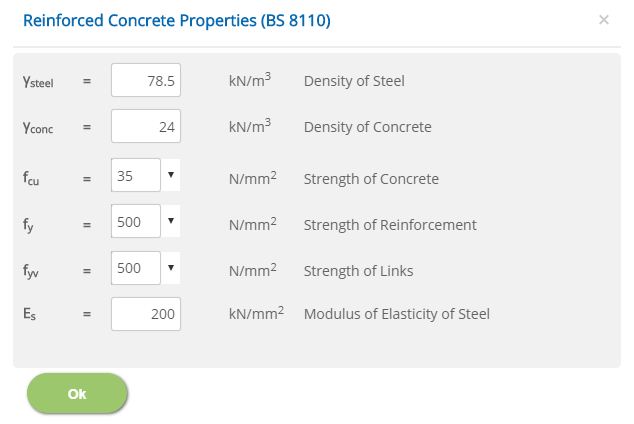
Density of Steel - γsteel
↔ Range: 70 to 80 kN/m3
Density of Concrete - γconc
↔ Range: 10 to 40 kN/m3
Strength of Concrete - fcu
↔ Range: 15 to 100 N/mm2
Strength of Reinforcement / Links - fy, fyv
↔ Range: 150 to 2000 N/mm2
Modulus of Elasticity of Steel - Es
↔ Range: 50 to 300 kN/mm2
Reinforced Concrete Properties (BS EN 1992-1-1)
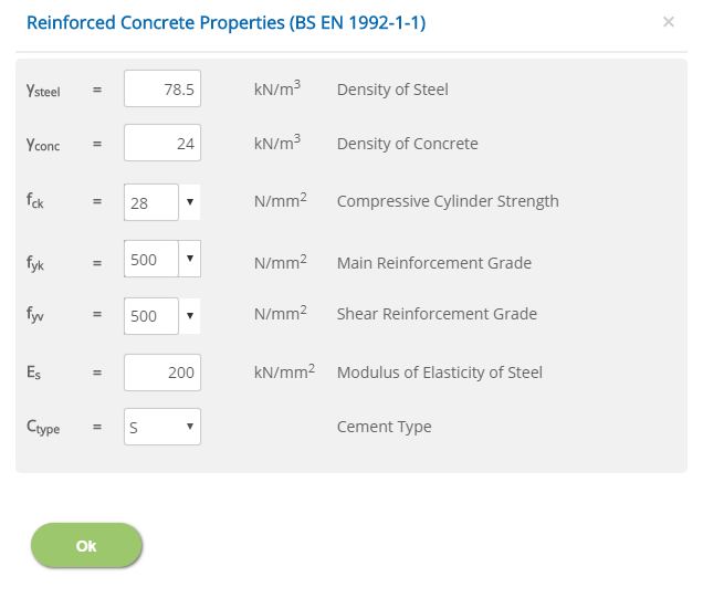
Density of Steel - γsteel
↔ Range: 70 to 80 kN/m3
Density of Concrete - γconc
↔ Range: 10 to 40 kN/m3
Compressive Cylinder Strength - fck
↔ Range: 15 to 100 N/mm2
Main / Shear Reinforcement Grade - fyk, fyv
↔ Range: 150 to 2000 N/mm2
Modulus of Elasticity of Steel - Es
↔ Range: 50 to 300 kN/mm2
Reinforced Concrete Properties (ACI 318M)
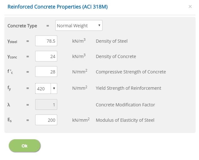
Density of Steel - γsteel
↔ Range: 70 to 80 kN/m3 (450 to 520 pcf)
Density of Concrete - γconc
↔ Range: 10 to 40 kN/m3 (60 to 265 pcf)
Compressive Strength of Concrete - f'c
↔ Range: 15 to 100 N/mm2 (1 to 6 ksi)
Yield Strength of Reinforcement - fy
↔ Range: 150 to 2000 N/mm2 (20 to 300 ksi)
Concrete Modification Factor - λ
↔ Range: 0.75 to 1
Modulus of Elasticity of Steel - Es
↔ Range: 50 to 300 kN/mm2 (7000 to 45000 ksi)
Material Partial Safety Factors
Enter the material safety factors on selection of British or European Standard and Design Unit from Design Option.
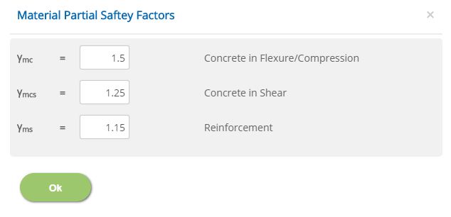
Concrete in Flexure/Compression / Concrete in Shear / Reinforcement
γmc, γmcs, γms
↔ Range: 1 to 2
Stability Safety Factors
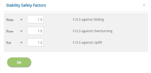
F.O.S against Sliding / Overturning / Uplift
γslide, γover, γup
↔ Range: 1 to 5
National Annex
Select the National Annex after selecting the European Standard in Design Option.
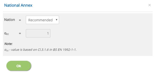
Nation
Select the National Annex option for the relevant factors to be considered in the design.
αcc
Enter the value for the User Defined National Annex option. For other options, this is not editable.
↔ Range: 0.7 to 1.2
Error Handling
Errors and Warnings are generated to prevent any inadvertent error in the input data. This section describes how to handle the errors and warnings. These errors are displayed at the bottom of the input page when the data in one or more input fields invalidate each other.
- Note: Out of range errors are displayed next to the input field.
| # | Error | Reason | Solution |
|---|---|---|---|
| 1 | Warning : Anchor Bolt placed closely with Tank, Minimum clearance to be provided | The minimum distance between Anchor Bolt and Tank Shell is not maintained. | Check and change the Bolt Centre Diameter (Dbcd) (or) Tank Inner Diameter (Di). |
| 2 | Warning : Minimum Edge Distance of 4 * Bolt Dia to be provided | Minimum edge distance is insufficient. | Check and change the Bolt Centre Diameter (Dbcd) (or) Tank Inner Diameter (Di) (or) Width of Ring Beam (Ww). |
| 3 | Warning : Minimum Edge Distance of 6 * Bolt Dia to be provided | Minimum edge distance is insufficient. | Check and change the Bolt Centre Diameter (Dbcd) (or) Tank Inner Diameter (Di) (or) Width of Ring Beam (Ww). |
| 4 | Warning : Grade Slab Thickness (Tg) must be lesser than Depth of Ring Beam | Thickness of grade slab is more than the depth of the ring beam. | Check and change thickness of grade slab (Tg) (or) Depth of foundation (Df) (or) Height ring beam / wall above ground (Hag). |
| 5 | Warning : Hard Stratum Depth (Hsd) can not be less than Depth of foundation (Df) | Depth of hard stratum is lesser than the Depth of foundation. | Check and change Hard Stratum Depth for settlement (Hsd) (or) Depth of foundation (Df). |
| 6 | Warning : Effective Diameter (Deff) shall not be greater than 1.5 times Tank Diameter (Di) | Effective diameter is greater than 1.5 times tank diameter. | Check and change effective diameter (Deff) (or) Tank Inner Diameter (Di). |
| 7 | Warning : Warning: Effective Height (Heff) shall not be greater than 1.5 times Tank Height (Ht) + (Hr) | Effective height is greater than 1.5 times tank height. | Check and change effective height (Heff) (or) Tank Shell Height (Ht) + (Hr) |
| 8 | Warning : Effective Diameter Cannot be Less than Tank Diameter | Effective diameter is lesser than the diameter of the tank. | Increase the effective diameter or decrease the diameter of the tank. |
| 9 | Warning : Effective Height Cannot be Less than Tank Height | Effective height is lesser than the height of the tank. | Increase the effective height or decrease the height of the tank. |
| 10 | Error : Hard Stratum Depth (Hsd) can not be greater than HSDMax | Hard stratum depth is greater than the maximum allowable limit. | The maximum hard strata depth criteria are recommended as 5 * Breadth of Foundation (Ww + Wfi + Wfo). |
| 11 | Error : Anchor Bolt Can't be placed inside Tank | Anchor bolt is located inside the tank. | Check and change the Bolt Centre Diameter (Dbcd) (or) Tank Inner Diameter (Di) and locate the anchor bolt outside the tank |
| 12 | Error : Bars are Closely placed. Height (h) of the Section should be > effective cover ( (2 * Cover) + Sum of Bar Dia) | Reinforcement bars are closely placed. Height of the section is lesser than the cover and reinforcement bars provided. | Check and change Depth of foundation (Df) (or) Height of ring beam / wall above ground (Hag) or Clear Cover Concrete. |
| 13 | Error : Bars are closely placed. Breadth (b) of Section should be > effective cover ( (2 * Cover) + Sum of Bar Dia) | Reinforcement bars are closely placed. Breadth of the section is lesser than the cover and reinforcement bars provided. | Check and change Width of ring beam / wall (Ww) or Clear Cover Concrete. |
| 14 | Error : Footing Bars are closely placed. Thickness (Tf) of Section should be > (2 * Cover) + Sum of Bar Dia | Footing reinforcement bars are closely placed. Thickness of the section is lesser than the cover and reinforcement bars provided. | Check and change thickness of footing (Tf) (or) Clear concrete cover for footing (Cfoot) |
| 15 | Error : Grade Slab Bars are closely placed. Thickness (Tg) of Section should be > (2 * Cover) + Sum of Bar Dia | Grade slab reinforcement bars are closely placed. Thickness of the section is lesser than the cover and reinforcement bars provided. | Check and change thickness of grade slab (Ts) (or) Clear concrete cover for footing (Cgs) |
| 16 | Error : Anchor Bolt Can not lie beyond the Ring Beam | Anchor bolt is located beyond the ring beam. | Check and change the Bolt Centre Diameter (Dbcd) (or) Tank Inner Diameter (Di) (or) Width of Ring Beam (Ww). |
| 17 | Error : Operating Liquid Level Height should not exceed Tank Height | Height of operating liquid is greater than the height of the tank. | Increase height of the tank or decrease the height of operating liquid. |
| 18 | Error : Test Liquid Level Height should not exceed Tank Height | Height of test liquid is greater than the height of the tank. | Increase height of the tank or decrease the height of test liquid. |
| 19 | Error : Width of Ring Beam in Contact with Fluid should not exceed Width of Ring Beam | Width of ring beam in contact with fluid provided is greater than the width of the ring beam. | Check and change Width of ring beam / wall (Ww) (or) Tank Inner Diameter (Di) (or) Width of Ring Beam / Wall in contact with fluid (Wwf). |