> >
RC Retaining Wall Design
|
|
Download Sample Report |
The scope of this calculation module is to design a retaining wall for the given load cases. The section’s stability and moment capacity are checked for predetermined SLS and ULS combinations respectively. The design is further checked for crack width and shear.
Rankine's theory
ECPLUS DESIGN adopts the Rankine's theory for pressure calculation to design retaining wall:
Active earth pressure,
Ka = (1 - sin(δ)) / (1 + sin(δ))
Passive earth pressure,
kp = (1 + sin(δb)) / (1 - sin(δb))
Cohesion passive pressure,
Kpc = 2 * Kp1/2
δ - Angle of friction for retained material
δb - Angle of friction for base material
Features
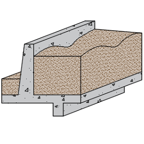
- The retaining wall design module allows the user to edit the geometry as well as properties of the components by giving various options such as,
- Wall type
- This option, helps the user to choose the wall geometry as required.
- Uniform
- Varying inside (slope of stem will be facing heel portion)
- Varying outside (slope of stem will be facing toe portion)
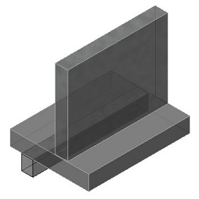
- Shear key provision
- Based on the design requirements the user can choose whether or not to provide shear key.
- Angle of soil surface
- This input enables the user to replicate actual site conditions by giving angular slope to the retained soil thus providing accurate results for the design requirements.
- Crack width check
- The program also checks for crack width of each component separately for the predefined SLS combinations.
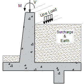
- The module allows the user to apply vertical, horizontal loads and moments directly on top of the stem.
Design Considerations
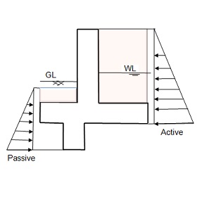
- All earth pressure forces are considered to act on a vertical plane, which passes through the interior end of base slab.
- Water table position and its effect on backfill is considered for design calculations.
- Rankine’s theory has been followed for calculating active and passive pressure coefficients.
- Bearing pressure and stability factors (sliding and overturning) are computed for the predefined load combinations and compared with allowable limit (user defined).
- The calculation is further proceeded only if the factor of safety for overturning check is > 1.
- Moments acting on the stem, toe, heel and shear key are computed for predefined load combinations and will be compared with actual moment capacity of the section.
- For crack width calculation, moments computed using SLS shall be used.
- The module checks for allowable shear stress against the design shear stress.
National Standards Available
British Standard
References
- BS 8002:1994 - Code of practice for Earth retaining structures.
Revision
- Ver 1.0 - Original version
|
|
Download Sample Report |