Help Topics
ECRETAIN - Reinforced Concrete Retaining Wall Design
This part of user manual describes how to use ECRETAIN for the design of Reinforced Concrete Retaining Wall. ECPlus applications are designed as wizard type which is a step by step guided input procedure. If you are new to ECPlus applications, click here for general guidance.
Prerequisites: The user is expected to have a basic understanding of foundation design concepts.
The minimum input data required to use this application is as follows:
- ❶ Dimension and Material Properties
- ❷ Concrete and Reinforcement Grades
- ❸ Allowable safety factors
- ❹ Crack width and its limit
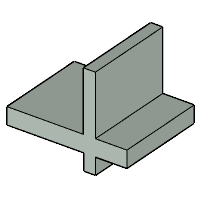
Stem
This page allows to enter stem details for the retaining wall.
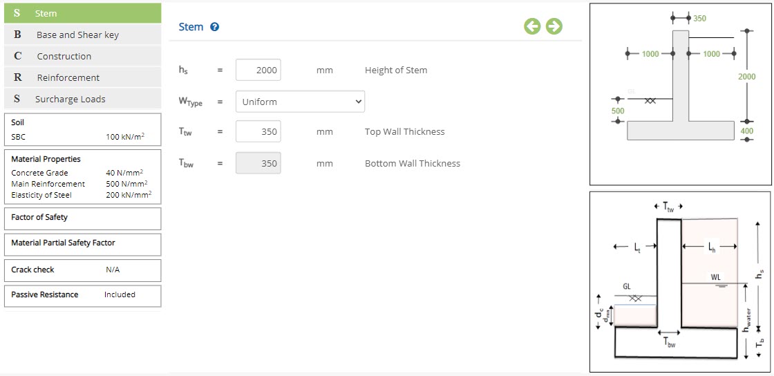 Height of Stem - hs
Enter the height of the stem.
↔ Range: 1000 to 20000 mm
▽ Uniform: Select this option to design wall with uniform thickness.
▽ Varying Inside: Select this option to provide bottom wall thickness higher than top wall thickness with varying thickness inside.
▽ Varying Outside: Select this option to provide bottom wall thickness higher than top wall thickness with varying thickness outside.
Enter the thickness of wall on top.
↔ Range: 150 to 1000 mm
Enter the thickness of wall on bottom.
↔ Range: 150 to 1000 mm
Base and Shear key
This page allows to enter base and Shear key details for the retaining wall.
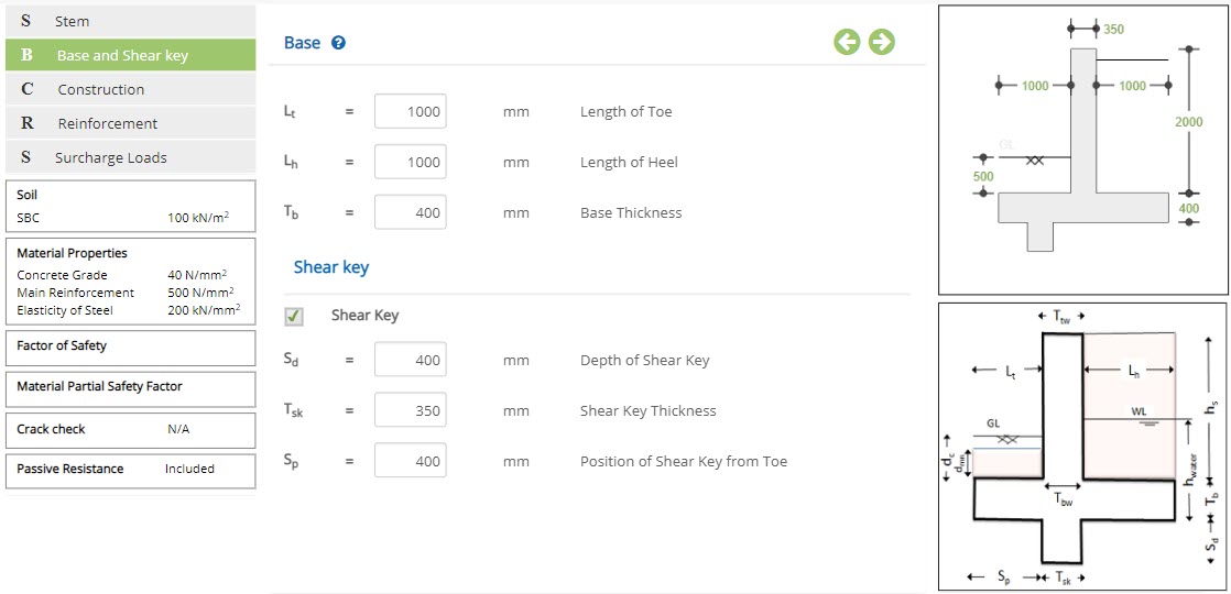
Base
Length of Toe - LtEnter the length of the toe.
↔ Range: 10 to 10000 mm
Enter the length of the base heel.
↔ Range: 10 to 10000 mm
Enter the thickness of base.
↔ Range: 150 to 1000 mm
Shear Key
☐ Shear KeyEnable this option to provide shear key to the retaining wall.
Depth of Shear Key - SdIf shear key above is enabled, enter the depth of the shear key.
↔ Range: 10 to 1000 mm
If shear key above is enabled, enter the thickness of the shear key.
↔ Range: 150 to 1000 mm
If shear key above is enabled, enter the location of the shear key, from bottom left of base.
↔ Range: 0 to 10000 mm
Construction
This page allows to enter construction data for the retaining wall.
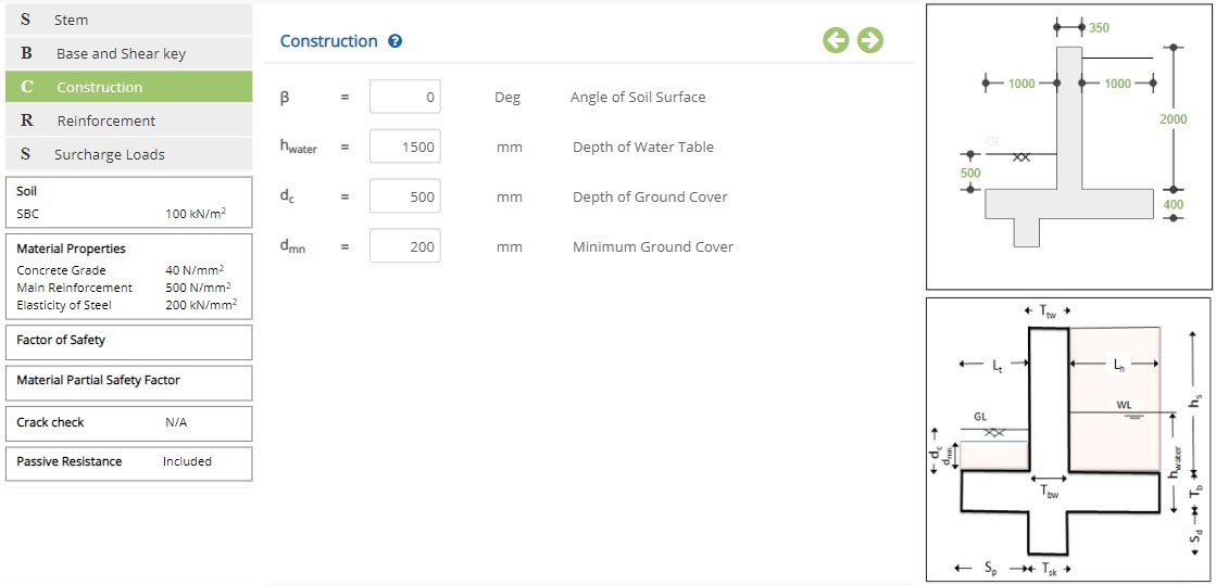 Angle of Soil Surface - β
Enter the angle of soil surface.
↔ Range: 0 to 50 Deg
Enter the depth of water table from bottom of base.
↔ Range: 0 to 20000 mm
Enter the depth of ground cover from top of base.
↔ Range: 0 to 5000 mm
Enter the minimum ground cover from top of base.
↔ Range: 0 to 5000 mm
Reinforcement
This page allows to enter reinforcement data for the retaining wall.
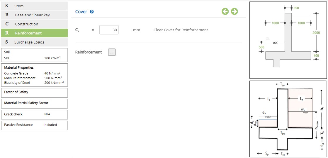 Clear Cover for Reinforcement - Cc
Enter the clear cover for reinforcement.
↔ Range: 15 to 80 mm
Click this popup to open reinforcement details popup.
Reinforcement
Click the reinforcement button to open the reinforcement details pop-up for retaining wall.
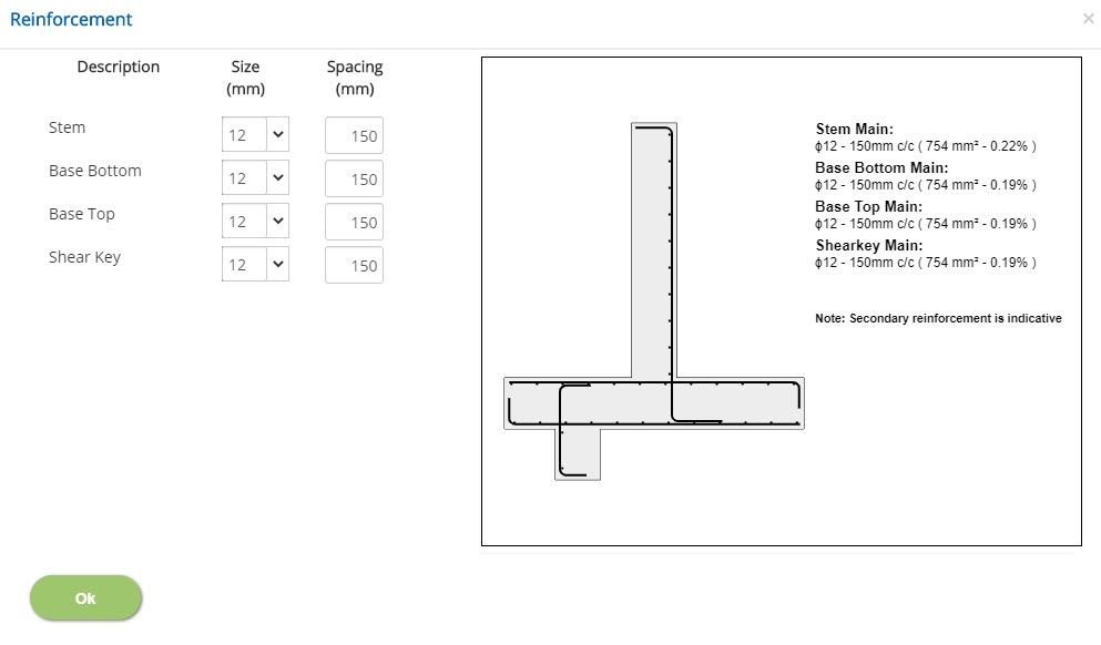 Size
SizeSelect the size of bar used in stem, base bottom, base top and shear key.
↔ Range: 4 to 50 mm
Select the spacing between bars used in stem, base bottom, base top and shear key.
↔ Range: 20 to 450 mm
Surcharge Loads
This page allows to enter surcharge loads for the design of retaining wall.
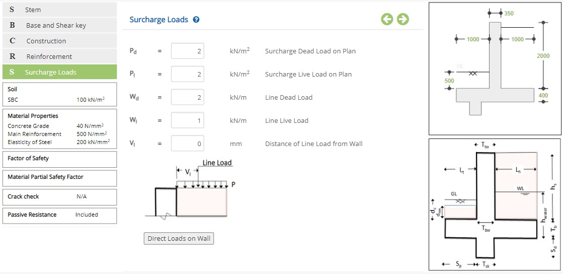 Surcharge Dead Load on Plan - Pd
Enter the surcharge due to dead load.
↔ Range: 0 to 100 kN/m2
Enter the surcharge due to live load.
↔ Range: 0 to 100 kN/m2
Enter the line dead load.
↔ Range: 0 to 100 kN/m2
Enter the line live load.
↔ Range: 0 to 100 kN/m2
Enter the distance of line load acting from wall.
↔ Range: 0 to 10000 mm
Direct Loads on Wall
This popup allows to enter any direct loads acting on wall.
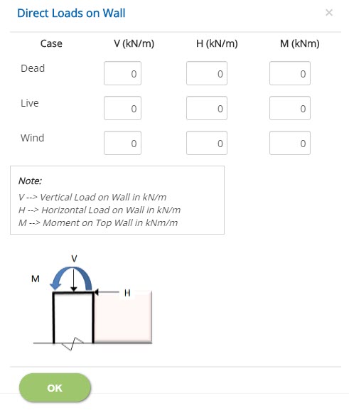 Vertical Load on Wall - V
Enter the vertical dead, live and wind load acting on the wall.
↔ Range: 0 to 1000 kN/m
Enter the horizontal dead, live and wind load acting on the wall.
↔ Range: 0 to 1000 kN/m
Enter the moment due to dead, live and wind load acting on the wall.
↔ Range: 0 to 1000 kNm
Design Setting
Setting for various Design Data such as Soil, Concrete and Material and Safety Factors are presented in this section. This setting pop-up can be accessed by clicking the bottom panel below the left navigation.
Soil
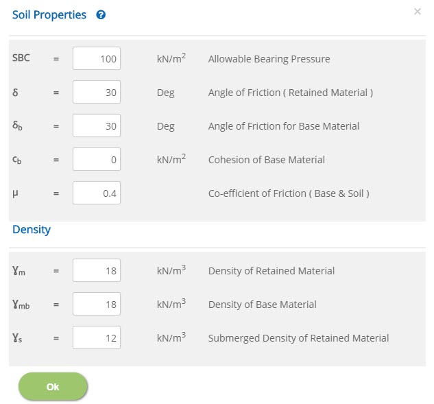 Allowable Bearing Pressure - SBC
↔ Range: 50 to 500 kN/m2
Angle of Friction ( Retained Material ) - δ↔ Range: 0 to 90 Deg
Angle of Friction for Base Material - δb↔ Range: 0 to 50 Deg
Cohesion of Base Material - cb↔ Range: 0 to 100 kN/m2
Co-efficient of Friction ( Base & Soil ) - µ↔ Range: 0.1 to 1
Density of Retained Material - Ɣm↔ Range: 10 to 50 kN/m3
Density of Base Material - Ɣmb↔ Range: 10 to 50 kN/m3
Submerged Density of Retained Material - Ɣs↔ Range: 10 to 50 kN/m3
Material Properties
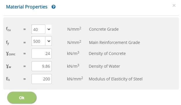 Concrete Grade - fcu
↔ Range: 12 to 100 N/mm2
Main Reinforcement Grade - fy↔ Range: 200 to 600 N/mm2
Density of Concrete - Ɣconc↔ Range: 16 to 30 kN/m3
Density of Water - ƔW↔ Range: 1 to 15 kN/m3
Modulus Elasticity of Steel - Es↔ Range: 50 to 300 kN/mm2
Factor of Safety
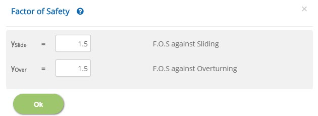 F.O.S against Sliding - γSlide
↔ Range: 1 to 5
F.O.S against Overturning - γOver↔ Range: 1 to 5
Material Safety Factor
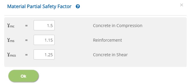 Concrete in Compression - γmc
↔ Range: 1 to 2
Reinforcement - γms↔ Range: 1 to 2
Concrete in Shear - γmcs↔ Range: 1 to 2
Crack Width
This popup allows to select options for crack width calculation.
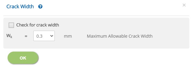
☐ Check for crack width
Enable this option to include crack width check in calculation.
Select the maximum allowable value for crack width from the drop down.
Passive Resistance
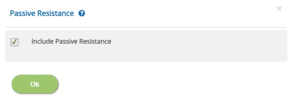
☐ Include Passive Resistance
Enable this option to include passive resistance in calculation.
Error Handling
Errors and Warnings are generated to prevent any inadvertent error in the input data. This section describes how to handle the errors and warnings. These errors are displayed at the bottom of the input page when the data in one or more input fields invalidate each other.
- Note: Out of range errors are displayed next to the input field.
| # | Error | Reason | Solution |
|---|---|---|---|
| 1 | Warning : dmn is exceed dc so dmn value is taken as dc value | Minimum ground cover is greater than the depth of ground cover provided. | Minimum ground cover will be taken same as depth of ground cover provided. |
| 2 | Error : Sp Should be lesser than Overall Base Length | Position of shear key from toe is greater than the overall length of the base. | Increase overall length of base or decrease position of shear key from toe. |
| 3 | Error : hwater Should not be greater than Effective Height | Height of water is greater than the effective height. | Increase effective height or decrease height of water. |
| 4 | Error : dmn Should be lesser than Stem Height | Minimum ground cover is greater than the stem height. | Increase stem height or decrease minimum ground cover. |
| 5 | Error : dc Should be lesser than Stem Height | Depth of ground cover is greater than the stem height. | Increase stem height or decrease depth of ground cover. |
| 6 | Error : Tb Should be greater than twice the Effective Cover 2 * ( Cc + Dtoe) | Base thickness is not enough to accommodate provided toe reinforcement and clear cover. | Increase base thickness or provide toe reinforcement and clear cover accordingly. |
| 7 | Error : Tb Should be greater than twice the Effective Cover 2 * ( Cc + Dheel) | Base thickness is not enough to accommodate provided heel reinforcement and clear cover. | Increase base thickness or provide heel reinforcement and clear cover accordingly. |
| 8 | Error : Tsk Should be greater than twice the Effective Cover 2 * ( Cc + Dsk) | Shear key thickness is not enough to accommodate provided shear key reinforcement and clear cover. | Increase shear key thickness or provide shear key reinforcement and clear cover accordingly. |
| 9 | Error : Ttw Should be greater than twice the Effective Cover 2 * ( Cc + Dstem) | Top wall thickness is not enough to accommodate provided stem reinforcement and clear cover. | Increase top wall thickness or provide stem reinforcement and clear cover accordingly. |
| 10 | Error : Top Wall Thickness(Ttw) Should be lesser than or equal to Bottom Wall Thickness (Tbw) | Top wall thickness is greater than the bottom wall thickness. | Provide top wall thickness greater than or same as bottom wall thickness. |
| 11 | Error : Vl Position of Applied Vertical Load Should be lesser than Length of Heel | Distance of line load from wall is greater than the length of the heel. | Increase length of the heel or decrease the distance of line load from wall. |
| 12 | Error : Vl Position of Applied Vertical Load Should be lesser than Length of Heel | Distance of line load from wall is greater than the length of the heel. | Increase length of the heel or decrease the distance of line load from wall. |