Help Topics
ECMAT - Mat Foundation Design
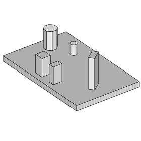
This part of user manual describes how to use ECMAT for the design of Mat Foundations with single or multiple pedestals. ECPlus applications are designed as wizard type which is a step by step guided input procedure. If you are new to ECPlus applications, click here for general guidance.
Prerequisites: The user is expected to have a basic understanding of foundation design concepts.
The minimum input data required to use this application is as follows:
- ❶ Soil data such as Safe Bearing Capacity and ground water table.
- ❷ Allowable stability factors
- ❸ Concrete and Reinforcement Grades
- ❹ Pedestal Dimensions
- ❺ Foundation Loads
Technical reference for ECMat can be found here.
Following sections are presented with various input pages of ECMAT application with descriptions:Design Options
This page allows to select the foundation support system, i.e. soil or pile, design standard and unit.
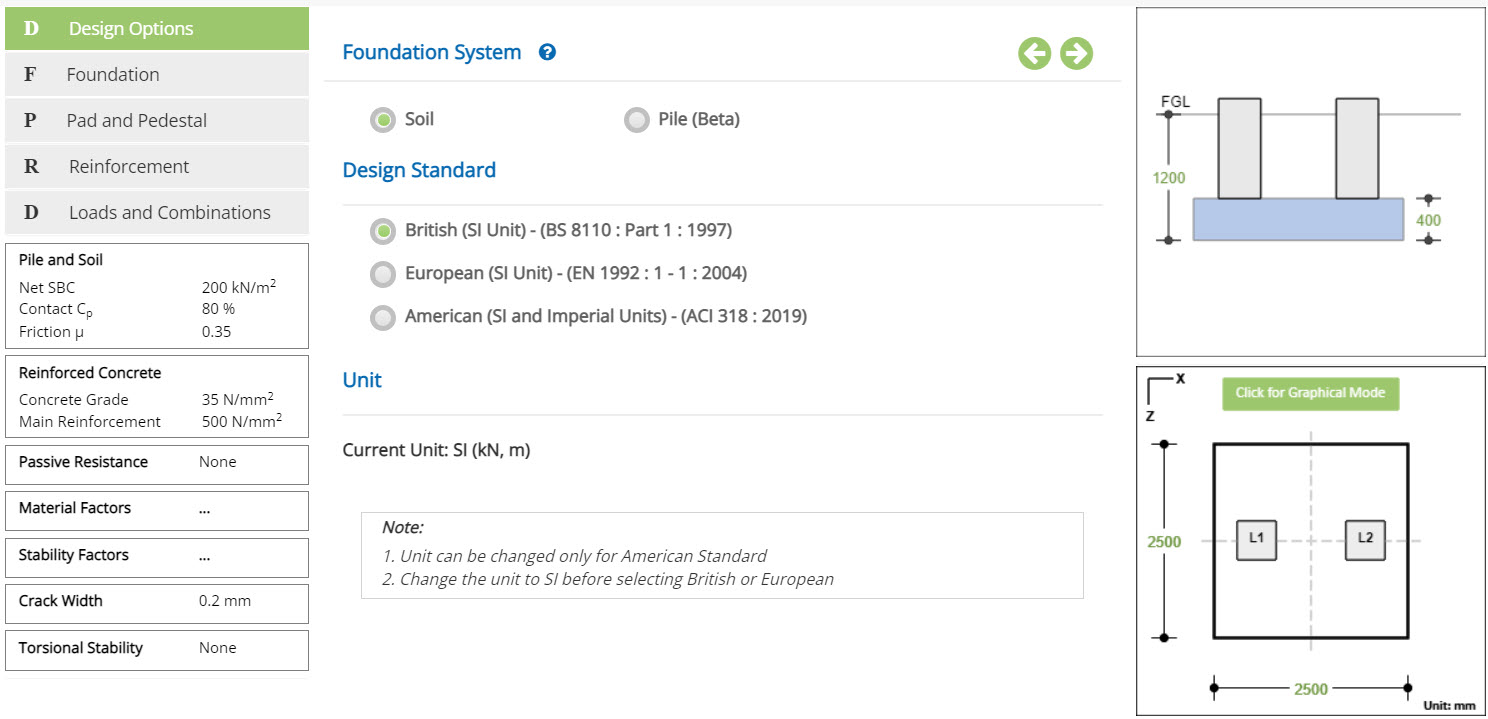
Foundation System
Select if the foundation is supported on Soil or Pile
Design Standard
Select the National Standard for the design. Available Standards: ☉British, ☉European and ☉American.
Unit
Displays the active design unit. The unit Change button is displayed when ☉American Standard is selected.
British or European Standard can not be selected when Imperial unit is active.
Change
Click this button to open the unit change pop-up dialog.
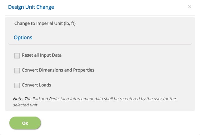
☐ Reset all Input Data
Check this option to reset the input data for the new unit. This option is recommended if the job is new and no input data has been entered before.
☐ Convert Dimensions and Properties
Check this option to convert all the previously entered input data except Load data to the new unit.
☐ Convert Loads
Check this option to convert previously entered load data to the new unit.
Note: Both Convert Dimensions and Properties and Convert Loads options can be used simultaneously to convert all the previously entered input values to the new unit.
- Note: While the program attempts to reasonably convert the reinforcement sizes equivalent to the new unit, the user should, however, verify the reinforcement pages of pad and pedestal to ensure that the conversion has been applied as expected.
Incorrect option selection leads to out of range errors and should be manually corrected.
Foundation
This page allows the input of foundation data such as depth of the foundation and depth of the water table below the ground level.
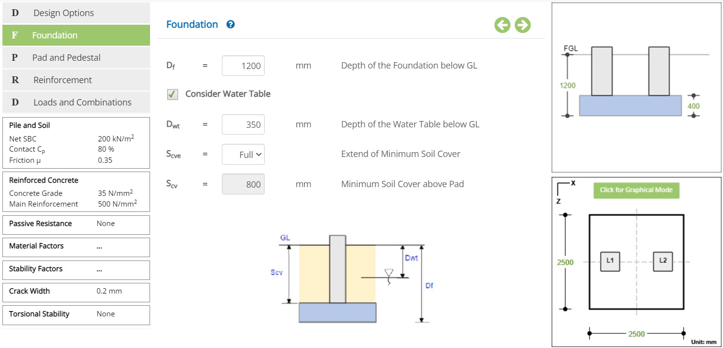 Depth of Foundation
Enter the depth of the foundation pad below the finished ground level. Blinding concrete thickness should not be included in this depth.
↔ Range: 0 to 5000 mm (0 to 200 inches)
Check this option to consider water table.
Depth of the Water Table below GLEnter the depth of the water table from the ground level. Presence of water table induces buoyancy effect and affects the stability of the foundation.
↔ Range: 0 to 5000 mm (0 to 200 inches)
Select the option from Nil, Full and Partial
▽ Nil: Select this option if the soil cover above pad is likely to be zero due to any adjacent excavation.
▽ Full: Select this option if the soil cover above pad is to be considered as full up to the ground level.
▽ Partial: Select this option to specify a partial soil cover.
Enter the minimum soil cover to be considered above Pad. This input is enabled when 'Extend of Minimum Soil cover' is selected with the option Partial. Any soil cover specified excess of available depth is ignored.
- Note: Program automatically calculates for two cases as one with minimum soil cover and another with full soil cover. Design results are reported for critical case.
Pad and Pedestal
This page allows to enter the Pad and Pedestal Dimensions and the locations of Pedestals on the Pad. Graphical Edit can also be used to enter the pad size and pedestal locations visually.
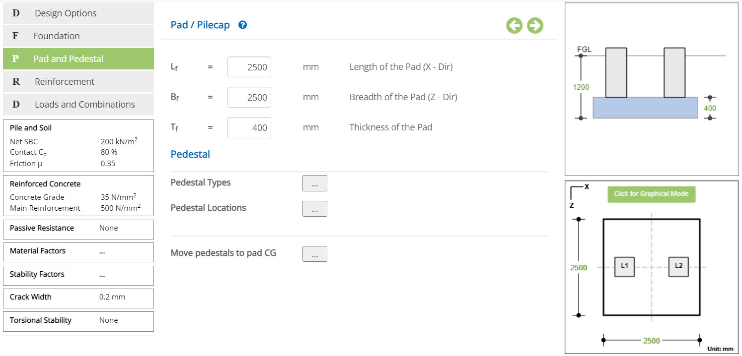
Pad
Length of the Pad (X-Dir) - LfEnter the dimension of the Pad in X direction.
↔ Range: 300 to 100000 mm (10 to 4000 inches)
Breadth of the Pad (Z-Dir) - Bf
Enter the dimension of the Pad in Z direction.
↔ Range: 300 to 100000 mm (10 to 4000 inches)
Thickness of the Pad - Tf
↔ Range: 100 to 10000 mm (4 to 400 inches)
Move pedestals to pad CG
Click on this button to move pedestals in accordance with CG of the pad.
Pedestal
The buttons Define Pedestal Types and Define Pedestal Locations are provided in this section.
Define Pedestal Types
Click this button to open the pop-up dialog and define the pedestal types and its dimensions. This is a spreadsheet type input dialog - right click on the spreadsheet to add or delete rows. Alternatively, the user can copy and paste data from an external source such as Microsoft Excel.
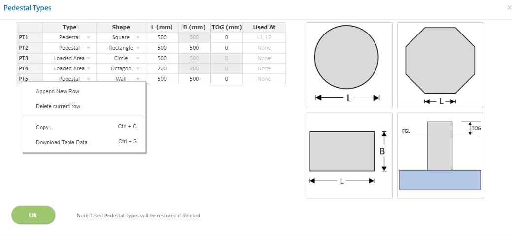
Type
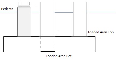
▽ Pedestal: Select this option when pedestal load is applied at a height above the ground level such as pedestal supporting a steel column.
▽ Loaded Area Top: Select this option when pedestal load is applied at the top of the Pad such as a concrete column supporting roof beams.
▽ Loaded Area Bot: Select this option when pedestal load is applied at the bottom of the Pad such as a concrete column supporting roof beams.
Shape
Select the shape of the pedestal from the available options Rectangle, Square, Circle, Octagon, Wall or Sleeper.
Length of the Pedestal (L)
Enter the length of the pedestal for the selected shape as defined in the picture.
↔ Range: 100 to 3000 mm (4 to 120 inches)
↔ Range: 100 to 12000 mm (4 to 480 inches) for walls
Breadth of the Pedestal (B)
Enter the breadth of the pedestal for the selected shape as defined in the picture.
↔ Range: 100 to 3000 mm (4 to 120 inches)
Top Of Ground level (TOG)
Enter the height of the pedestal above Ground Level. Not applicable for 'Loaded Area' Pedestal Type.
↔ Range: 0 to 6000 mm (0 to 240 inches)
Used at
Displays the pedestal locations on the pad where the pedestal type is used (Information only)
- Note 1: A single pedestal type can be used at multiple locations on the pad but the loads shall be input for each location. The design is presented for only the pedestal type. If required, user must define individual types even if the same size of pedestal but different reinforcement is required at different locations.
- Note 2: Any pedestal type which has been used at locations on pad can not be deleted. If any used pedestal type row is deleted, it will be reinstated after the pop-up has been closed. To delete a pedestal type, it must be first unassigned from any location on the pad.
Pedestal Locations
Click this button to open the pop-up dialog and define the pedestal locations with reference to the top left corner of the pad. This is a spreadsheet type input dialog - right click to add or delete rows. Alternatively, the user can copy and paste data from an external source such as Microsoft Excel.
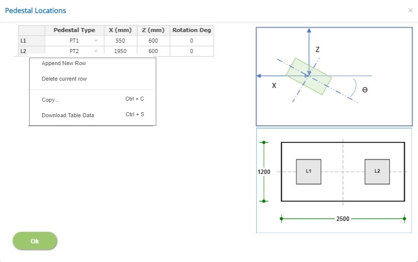
X / Y / Rotation (deg)
Enter the x and y co-ordinates to locate the pedestal on the pad and the angle at which the pedestal is rotated with respect to X axis as shown in the picture.
Pedestal Type
Choose the pedestal type from the list of pedestal types defined in Define Pedestal Types pop-up.
Pedestal locations can also be defined conveniently by Graphical Edit mode.
Reinforcement
This page allows to enter the clear cover to the rebars of Pad and Pedestals and define the reinforcement details.
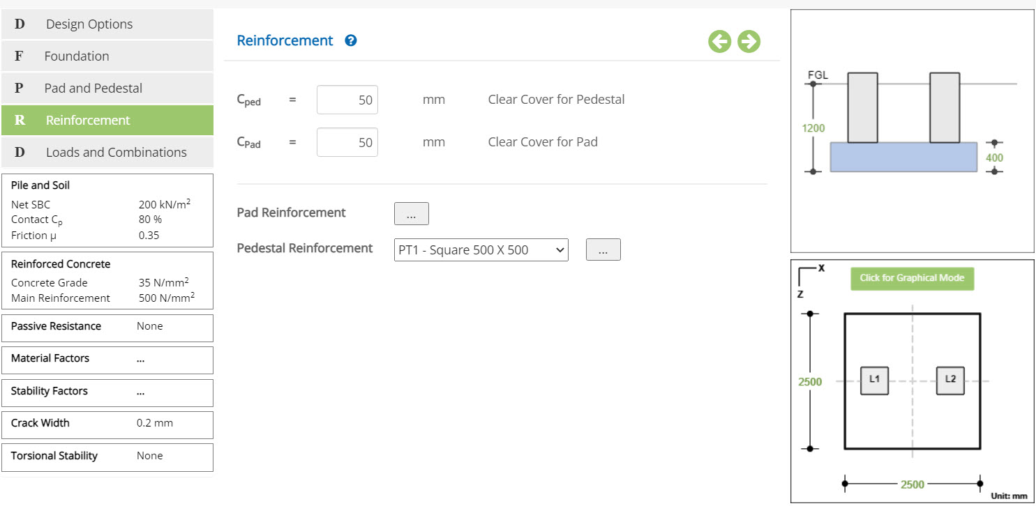
Clear Cover to Pedestal - Cped
Enter the clear cover for the Pedestal.
↔ Range: 15 to 150 mm (0.5 to 6 inches)
Clear Cover to Pad - Cpad
Enter the clear cover for the Pad.
↔ Range: 15 to 150 mm (0.5 to 6 inches)
Two buttons for Pad Reinforcement and Pedestal Reinforcement for each pedestal type defined in Define Pedestal Types pop-up are provided in this page.
Pad Reinforcement
click this button to open the pad reinforcement pop-up as follows:
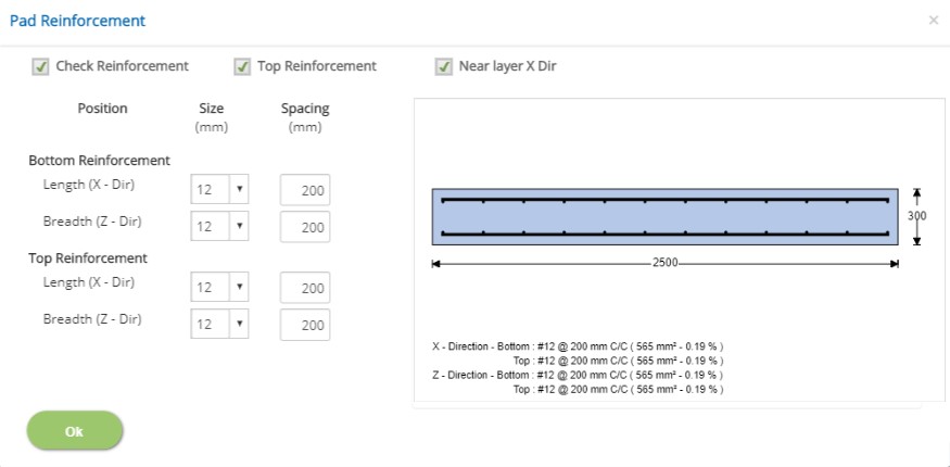
- ☐ Check Reinforcement
Check this option if the pad reinforcement design is required.
- ☐ Top Reinforcement
Check this option if the pad is provided with reinforcement at top.
- ☐ Near Layer X dir
Check this option if the rebars provided in the X direction is the first layer (near to the surface).
- Bottom Reinforcement / Top Reinforcement
Select the rebar diameter and enter spacing as required for each layer of reinforcement in both directions.
Pedestal Reinforcement
Click this button to open the pedestal reinforcement pop-up for the selected pedestal type as follows:
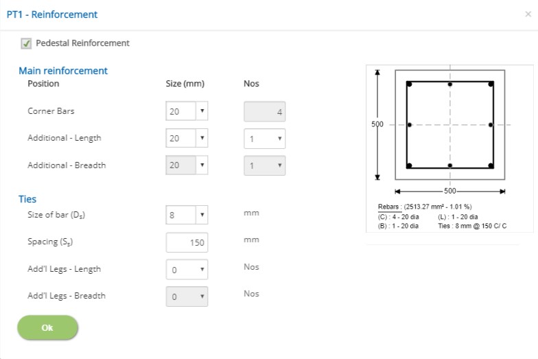
☐ Pedestal Reinforcement
Check this option if the pedestal reinforcement design is required. If the pedestal type is Loaded Area, reinforcement can not be defined.
Main Reinforcement / Ties
Reinforcement for main longitudinal bars and ties can be defined according to the shape of the pedestal.
Loads and Combinations
This page allows to define the load cases, SLS and ULS combinations. Allowable factor of safety for stability conditions, percentage of increase in safe bearing capacity for each combination are also defined in this page. Pedestal loads can be applied to according to the load convention of different structural analysis software.
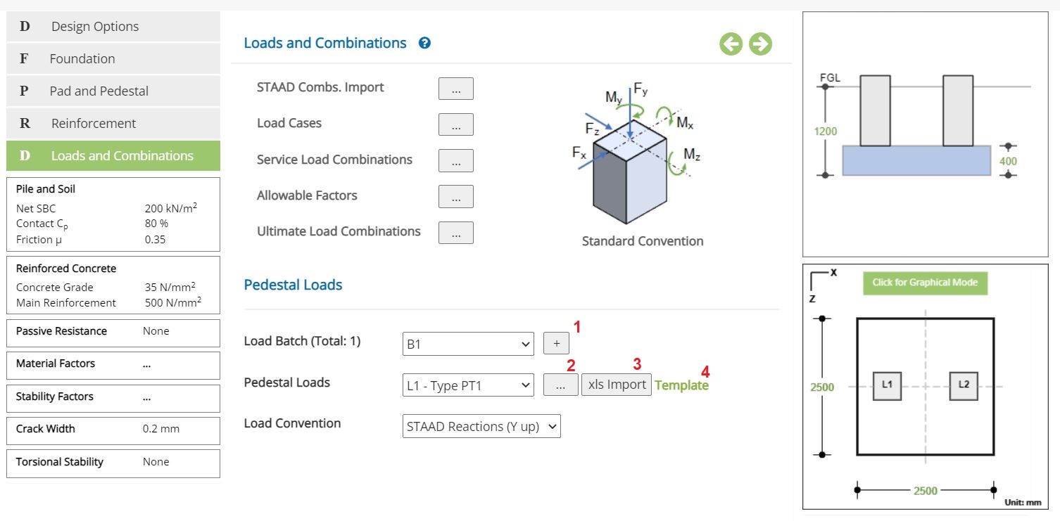
The following buttons are provided for pop-up dialog for the input data:
- STAAD Import of L&C
- Define Load Cases
- Service Load Combinations
- Allowable Load Factors
- Ultimate Load Combinations
- Pedestal Loads
Load Input Convention Options ☉STAAD Reactions (Y up), ☉STAAD Forces (Y up) and ☉Standard Convention are provided to facilitate the load import from various structural analysis software according to their convention.
STAAD Import of L&C
Click this button to open the pop-up dialog to import load cases and combinations from STAAD Input File. This is an optional import feature. User can skip this and define load cases and load combinations directly.
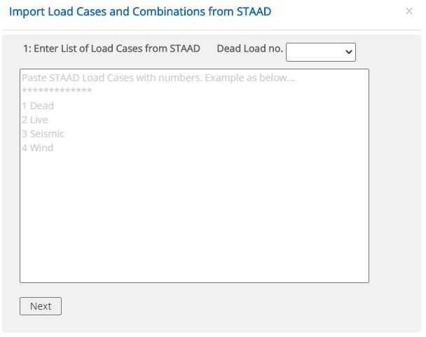
To import the load cases and combinations, follow the steps as below
1. Paste the load cases from STAAD with load case numbers
2. Select the Dead Load No, from the list box above
3. Click Next button
4. Paste the SLS load combinations from STAAD Input file
5. Click Next button
6. Paste the ULS load combinations from STAAD Input file
7. Click Next button
8. Click Finish button to complete the STAAD Import.
STAAD Imported load cases and combinations can be modified if required.
Define Load Cases
Click this button to open the load cases pop-up dialog. This is a spreadsheet type input dialog - right click to add or delete rows. Alternatively, the user can copy and paste the data from external source such as Microsoft Excel.
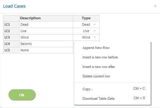
In this pop-up, n - number of load cases and its type can be defined.
Description
Enter the description of the load case. Do not duplicate the load case description since it is used as a reference to define the load combinations. This field can not be left blank and the special character '#' can not be used.
Type
Select the load type Dead, Live, Wind, Seismic, or Other. First load case type should be 'Dead'
- Note: Any row deletion, addition and modification will affect the load combinations and pedestal loads.
Service Load Combinations
Click this button to open the Service Load Combinations pop-up dialog. This is a spreadsheet type input dialog - right click to add or delete rows. Alternatively, the user can copy and paste the data from an external source such as Microsoft Excel.
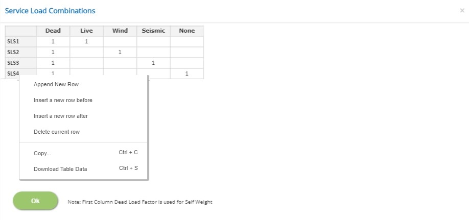
In this pop-up, n - number of Service Load Combinations (SLS) can be added with factors for each load case defined earlier.
Soil
Select the soil condition for the load combination
▽ Full: Select this combination if the soil cover is full and no passive pressure to be considered.
▽ Full + P: Select this combination if the soil cover is full and passive pressure to be considered.
▽ Min: Select this combination if the soil cover is minimum and no passive pressure to be considered.
▽ Min + P: Select this combination if the soil cover is minimum and passive pressure to be considered.
▽ Ignore: Select this combination if it is to be ignored in the analysis and design.
Load Cases Factors
Load Case Description is displayed in each spreadsheet column. Enter the load factor for every load case and for each load combination.
↔ Range: -10 to 10
- Note: For Dead Load case type, which is the first column, the factor should be a positive non-zero value.
Allowable Factors (SLS)
Click this button to open the allowable factors for Service Load Combinations pop-up dialog. This is a spreadsheet type input dialog but rows can not be deleted or added. The user can copy and paste the data from an external source such as Microsoft Excel.
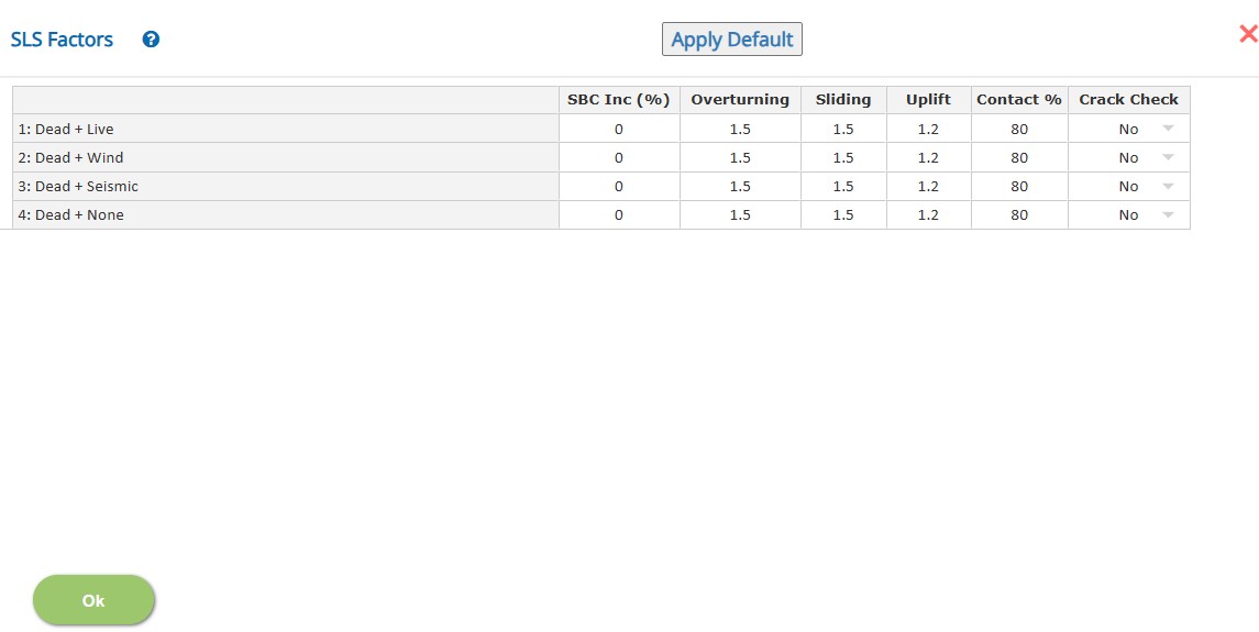
The first column header displays the service load combination according to the load factors defined in the service load combinations.
SBC Inc (%):
Enter the percentage of increase / decrease of safe bearing capacity for each service load combination. Negative value indicates decrease in allowable value.
↔ Range: -100 to 200
Overturning / Sliding / Uplift
Enter the allowable factor of safety for the stability type.
↔ Range: 1 to 10
Crack Width
Select if crack width is to be checked for each combination. If the crack width check option is not selected in Design Settings, no crack width check is carried out for any combination.
Ultimate Load Combinations
click this button to open the Ultimate load Combinations pop-up dialog. This is a spreadsheet type input dialog - right click to add or delete rows. Alternatively, the user can copy and paste the data from an external source such as Microsoft Excel.
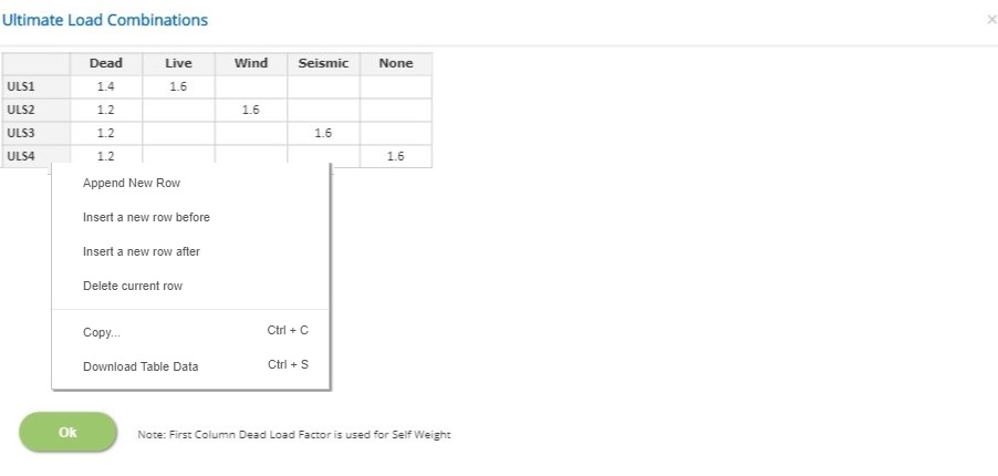
In this pop-up, n - number of Ultimate Load Combinations (ULS) can be added with factors for each load case defined earlier.
Soil
Select the soil condition for the load combination
▽ Full: Select this combination if the soil cover is full and no passive pressure to be considered.
▽ Full + P: Select this combination if the soil cover is full and passive pressure to be considered.
▽ Min: Select this combination if the soil cover is minimum and no passive pressure to be considered.
▽ Min + P: Select this combination if the soil cover is minimum and passive pressure to be considered.
▽ Ignore: Select this combination if it is to be ignored in the analysis and design.
Load Cases Factors
Load Case Description is displayed in each spreadsheet column. Enter the load factor for every load case and for each load combination.
↔ Range: -10 to 10
- Note: For Dead Load case type, which is the first column, the factor should be a positive non-zero value.
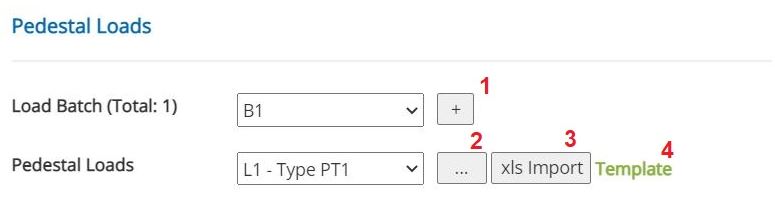 Load Batch (Total x)
Select the batch for which the pedestal loads are to be applied. To add or delete more batch loads use the button (1).
Pedestal LoadsSelect the pedestal location for which the loads are to be applied.
Click the button (shown as 3) to import the pedestal loads from an excel file (accepted formats .xls and .xlsx). This will allow the user to conveninently import the loads for all pedestal locations at once. The template for importing the loads from the excel file is available to download (shown as 4). The excel file to be imported shall have two sheets namely 'Locations' and 'Reactions'. The sheet 'Locations' defines the mapping of pedestal locations to the nodes for various batches. The sheet 'Reactions' shall have the reactions or foundation loads to be imported. The user must verify if the loads are propertly imported.
- Note1: Incorrect format leads to error or incorrect data import.
- Note2: Multi Load Batch Analysis is done for only for quick results. The detailed report is produced for the selected load batch.
Pedestal Loads
Click the button (shown as 2) to open the Pedestal Loads pop-up dialog for the selected Load Batch and selected Pedestal Location. This is a spreadsheet type input dialog but rows can not be deleted or added. Alternatively, the user can copy and paste the data from an external source such as Microsoft Excel.
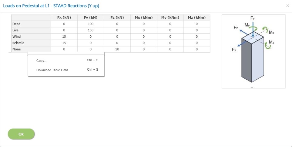
Load Components
Enter the loads Fx, Fy, Fz, Mx, My and Mz for the selected pedestal location for each load case according to the selected load convention.
↔ Range: -100000 to 100000
A picture is presented to indicate the active load convention (STAAD Reactions (Y Up), STAAD Forces (Y Up) or Standard Convention)
- Note: The load component My is included to the other shear force components to check the torsional stability of the foundation as an option.
Pedestal is not design checked for torsion.
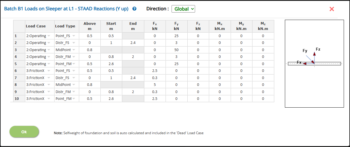
Sleeper Loads
Click the button (shown as 2) to open the Sleeper Loads pop-up dialog for the selected Load Batch and selected Pedestal Location where the selected Pedestal is Sleeper Type. This is a spreadsheet type input dialog and rows can be deleted or added. Alternatively, the user can copy and paste the data from an external source such as Microsoft Excel.
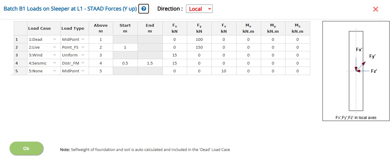
Direction
Select the load direction
▽ Global: Select this option to apply loads in the Global Direction irrespective of the rotation of the sleeper.
▽ Local: Select this option if the loads are to be applied to the axis of the sleeper (Loads will be resolved to the global directions during analysis and design).
Load Components
Enter the loads Fx, Fy, Fz, Mx, My and Mz for the selected pedestal location for each load case according to the selected load convention. For the distributed load type (Uniform, Distr_FS or Distr_FM), the loads will be per unit length
↔ Range: -100000 to 100000
Load Type
Select the load type and position with respect to the horizontal x axis
▽ MidPoint: Select this option if the point load is applied at the mid point (Unit kN, kN.m or kips, kips-ft).
▽ Point_FS: Select this option if the point load is applied at a distance from the left end (Unit kN, kN.m or kips, kips-ft).
▽ Point_FM: Select this option if the point load is applied at a distance from the mid point (Unit kN, kN.m or kips, kips-ft). Use negative value to apply the load to the left side from the mid point
▽ Uniform: Select this option if the load is applied as an uniformly distributed to the entire length of the sleeper (Unit kN/m, kN.m/m or kips/ft, kips-ft/ft)
▽ Distr_FS: Select this option if a discrete distributed load is applied - The start position is specified from the left end. (Unit kN/m, kN.m/m or kips/ft, kips-ft/ft)
▽ Distr_FM: Select this option if a discrete distributed load is applied - The start position is specified from the mid point. Use negative value for the start from the left side. (Unit kN/m, kN.m/m or kips/ft, kips-ft/ft)
↔ Range: -25 to 25
Load Positions
Enter the values to specify the position of the loads in horizontal x and vertical y axes
▽ Above: Enter the vertical offset (Unit m / ft) from top of the sleeper at which the load is applied. Positive value indicates the load is acting above the sleeper
▽ Start: Enter the start position (Unit m / ft) of the load (Applicable for Point_FS, Point_FM, Distr_FS and Distr_FM)
▽ Start: Enter the end position (Unit m / ft) of the load (Applicable for Distr_FS and Distr_FM)
↔ Range: -25 to 25
The user shall ensure the load positions are within the dimensions of the sleeper - The program does not warn if it falls out of sleeper.
A picture is presented to indicate the active load convention (STAAD Reactions (Y Up), STAAD Forces (Y Up) or Standard Convention)
- Note: The load component My is included to the other shear force components to check the torsional stability of the foundation as an option.
Sleeper is not design checked for torsion.
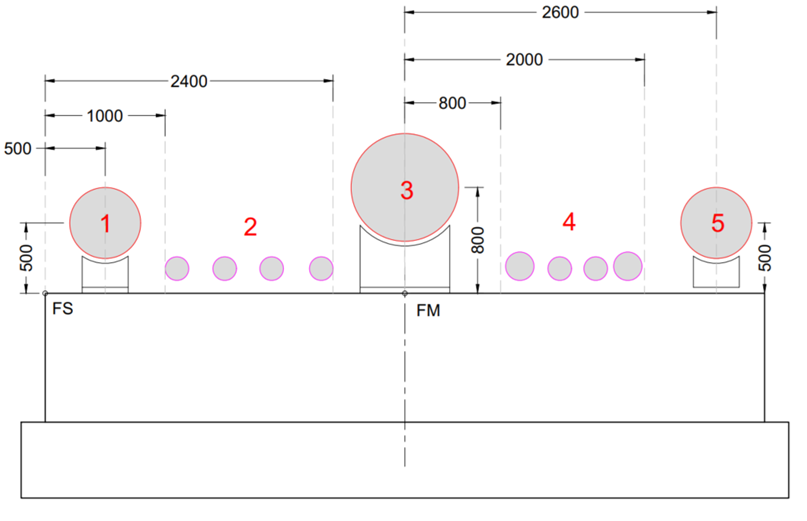
A sample pipe loads on the sleeper and the definition of the loads in the input are presented below for a quick reference
Graphical Mode:
The foundation size and the pedestal locations can also be modeled visually in Graphical Mode. Graphical Edit mode is invoked by clicking the right bottom picture of the input page.
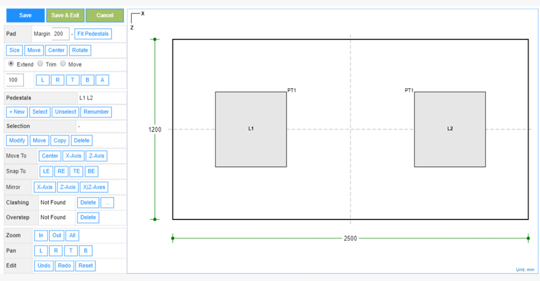
Click the pedestal locations on the picture to select and make the modification using the buttons given on the left side.
Buttons are provided for group selection, copying, rotating the pedestals and pad.
The Fit Pedestals button is to get the pad to the size encompassing all the pedestals with the margin specified.
The size of pad can be conveniently modified using the options Extend, Trim and Move and applying on sides of the pad L Left R Right B Bottom A All
- Note: If the picture is not fully visible, click the Zoom All button.
Design Setting
Setting for various Design Data such as Soil, Concrete, Passive Resistance and Material and Safety Factors are presented in this section. This setting pop-up can be accessed by clicking the bottom panel below the left navigation.
Pile and Soil
This pop-up is to define the soil or pile settings depending on the design option
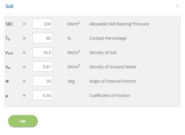
Select the Soil Data
▽ Fixed Select this option to directly specify the SBC and other associated parameters
▽ Table Select this option if the SBC and other associated parameters are varying according to the depth and size of foundation.
Allowable Net Bearing Pressure - SBC
↔ Range: 25 to 1000 kN/m2 (0.5 to 20 ksf)
Contact Percentage - Cp
Enter the percentage of minimum soil bearing area.
↔ Range: 10 to 100
Density of Soil - γsoil
↔ Range: 10 to 40 kN/m3 (60 to 250 pcf)
Density of Ground Water - γw
↔ Range: 5 to 15 kN/m3 (30 to 100 pcf)
Angle of Internal Friction - Φ
↔ Range: 0 to 60 deg
Coefficient of Friction - μ
Enter the coefficient of friction between the bottom of the pad and soil or any underlying media.
↔ Range: 0 to 1.5
Soil Table Data
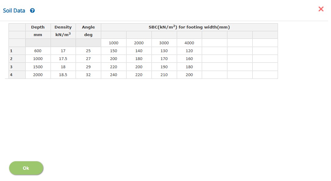
Define the depths and size of foundation and its corresponding soil parameters
The program will select the applicable SBC and other parameters based on the depth and size. (Parameters are interpolated for intermedicate values)
Pile
Pile properties and parameters such are dimension, spacing, working load, density are provided in this section.
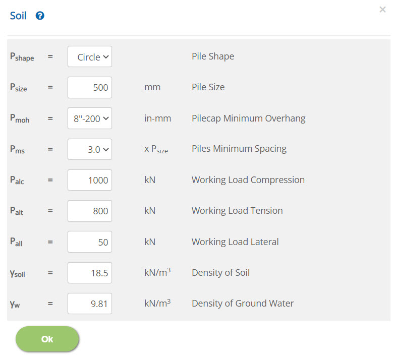 Pile Size - Psize
↔ Range: 100 to 3000 mm (4 to 120 inch)
Working Load Compression / Tension / Lateral - Palc / Palt / Pall↔ Range: 10 to 100000 kN (2 to 22500 kips)
Density of Soil - γsoil↔ Range: 10 to 40 kN/m3 (60 to 250 pcf)
Density of Ground Water - γw↔ Range: 5 to 15 kN/m3 (30 to 100 pcf)
Reinforced Concrete Properties (BS 8110)
Enter the reinforcement concrete properties on selection of British Standard from Design Option.
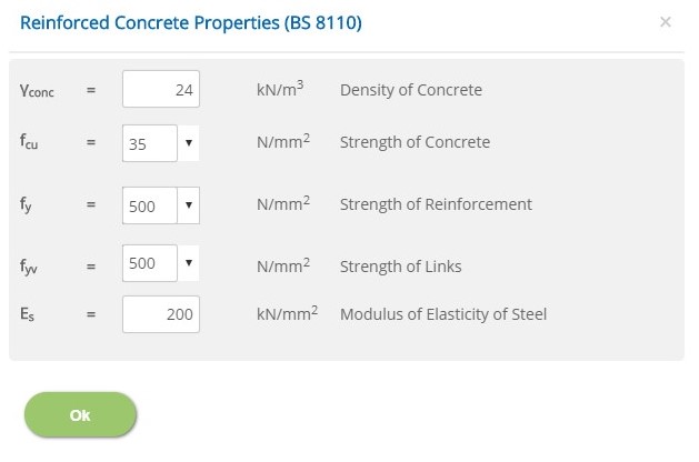
Density of Concrete - γconc
↔ Range: 10 to 40 kN/m3
Strength of Concrete - fcu
Enter characteristic strength of concrete.
↔ Range: 15 to 100 N/mm2
Strength of Reinforcement - fy
Enter characteristic strength of main reinforcement for pad and pedestal.
↔ Range: 150 to 2000 N/mm2
Strength of Links - fyv
Enter characteristic strength of links for pedestal.
↔ Range: 150 to 2000 N/mm2
Modulus of Elasticity of Steel - Es
↔ Range: 50 to 300 kN/m2
Reinforced Concrete Properties (BS EN 1992-1-1)
Enter the reinforcement concrete properties on selection of European Standard from Design Option.
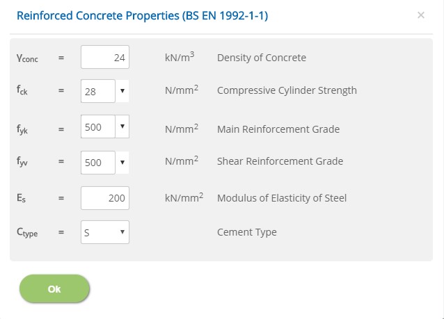
Density of Concrete - γconc
↔ Range: 10 to 40 kN/m3
Compressive Cylinder Strength - fck
↔ Range: 15 to 100 N/mm2
Main Reinforcement Grade - fyk
Enter grade of main reinforcement for pad and pedestal.
↔ Range: 150 to 2000 N/mm2
Shear Reinforcement Grade - fyv
Enter grade of shear reinforcement for pedestal.
↔ Range: 150 to 2000 N/mm2
Modulus of Elasticity of Steel - Es
↔ Range: 50 to 300 kN/mm2
Cement Type - Ctype
Select the cement class S, R or N
Reinforced Concrete Properties (ACI 318)
Enter the reinforcement concrete properties on selection of American Standard and Design Unit from Design Option.
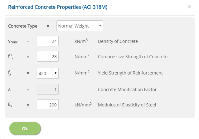
Density of Concrete - γconc
↔ Range: 10 to 40 kN/m3 (60 to 250 pcf)
Compressive Strength of Concrete - f'c
↔ Range: 15 to 100 N/mm2 (1 to 4 ksi)
Yield Strength of Reinforcement - fy
Enter yield strength of reinforcement for pad and pedestal.
↔ Range: 150 to 2000 N/mm2 (20 to 300 ksi)
Concrete Modification Factor - λ
↔ Range: 0.75 to 1
Modulus of Elasticity of Steel - Es
↔ Range: 50 to 300 kN/mm2 (7000 to 45000 ksi)
Passive Resistance
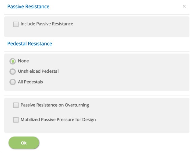
Passive Resistance
☐ Include Passive Resistance: Select if passive resistance is to be considered. Other options in the following have no effect if this is not selected.
Pedestal Resistance
☉ None: Select this option if passive resistance is not to be considered on pedestals.
☉ Unshielded Pedestals: Select this option if passive resistance is to be considered on pedestals which are fully or partially exposed to soil passive pressure without being shielded by others pedestals ahead in the direction of the shear force.
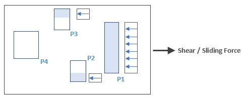
P1 - Fully unshielded pedestal
P2, p3 - Partially unshielded pedestals
P4 - Fully shielded pedestal
☉ All Pedestals: Select this option if passive Resistance is to be considered on pedestals irrespective of the shielding condition from other pedestals. User can select this option if it is presumed that all pedestals are fully effective in offering the passive resistance.
Other
☐ Passive Resistance on Overturning: Select this option if passive resistance is to be considered in resisting overturning. (By default only sliding is considered)
☐ Mobilized Passive Pressure for Design: Select this option if pedestals are to be designed for mobilized passive forces (Passive force generated due to applied shear forces).
Material Partial Safety Factors
Enter the material safety factors on selection of British or European Standard and Design Unit from Design Option.
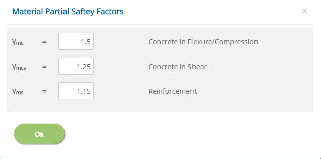
Flexure/Compression, Concrete in Shear, Reinforcement
γmc, γmcs, γms
↔ Range: 1 to 2
Stability Safety Factors
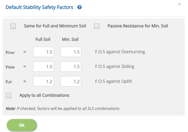
☐ Same for Full and Minimum Soil: Check this option to consider same allowable factors for both full and minimum soil conditions.
☐ Passive Resistance for Min. Soil: Check this option to consider passive resistance for minimum Soil condition.
Sliding, Overturning, Uplift
γslide, γover, γup
Enter the default factors of safety for these stability conditions. However, actual value for each load combination can be changed in Load Combination page.
↔ Range: 1 to 10
☐ Apply to all Combinations: Check this option to apply these factors to all SLS combinations.
Crack Width
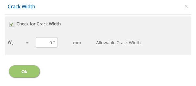
☐ Crack Width
Check this option if crack width is to be considered for Pad Design. However, for each load combination, this option can be changed in Load Combination page.
Allowable Crack Width - Wc
Enter the allowable crack width for the pad design.
↔ Range: 0.05 to 0.6 mm (0.002 to 0.024 in)
Torsional Stability Check
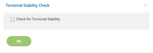
☐ Check for Torsional Stability
Check this option if torsional stability is to be considered for the foundation.
National Annex
Select the National Annex after selecting the European Standard in Design Option.
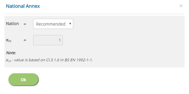
Nation
Select the National Annex option for the relevant factors to be considered in the design.
αcc
Enter the value for the User Defined National Annex option. For other options, this is not editable.
↔ Range: 0.7 to 1.2
Error Handling
Errors and Warnings are generated to prevent any inadvertent error in the input data. This section describes how to handle the errors and warnings. These errors are displayed at the bottom of the input page when the data in one or more input fields invalidate each other. Calculation can not be run if there is any error in the input data.
- Note: Out of range errors are displayed next to the input field.
| # | Error | Reason | Solution |
|---|---|---|---|
| 1 | Warning : Minimum Soil Cover exceeds available cover - Extra cover is ignored | Minimum Soil cover in the Foundation page is specified more than the available space. | Change the Extend of Minimum Soil Cover to Full or enter the value less than or equal to available space. Program, however, considers only available soil cover in the calculation. |
| 2 | Error : No Pedestal Location Found | All pedestal locations have been deleted in the Graphical Mode. | Use Graphical Edit mode to include at least one pedestal |
| 3 | Error : Clashing Pedestals | Pedestal Locations are specified such that two or more pedestals clash each other | Use Graphical Edit mode to relocate the pedestals visually |
| 4 | Error : Overstepping Pedestals | One or more pedestals are located outside the pad boundary. | Adjust the pad size or relocate the pedestals. |
| 5 | Error : Pedestal type dimension(s) out of range | While switching between units in ACI Standard, if Convert Dimensions and Properties option has not been selected, out of range error is triggered. | Open the Pad and Pedestals page to update the pedestal dimensions as per the selected unit. |
| 6 | Error : Insufficient Pad Thickness | Pad thickness is too small to accommodate the rebars with the specified Clear Cover | Check the clear cover in Reinforcement page or adjust the thickness of the pad in Pad and Pedestals page. |
| 7 | Error : TOG is inside the pad | A part of pad thickness is above ground level and TOG of any pedestal is inside the pad. | Check the pad thickness or TOG of any pedestal in Pad and Pedestals page. |
| 8 | Error : Soil Settings Parameter(s) out of range | While switching between units in ACI Standard, if Convert Dimensions and Properties option has not been selected, out of range error is triggered. | After switching between the units, soil setting data should be verified and modified according to the selected unit. |