> >
Horizontal Equipment Foundation Design
|
|
Download Sample Report |
The scope of this calculation module (ECHORVES) is to analyse and design a foundation for a horizontal equipment with combined or isolated footing type for Serviceability (SLS) and Ultimate (ULS) load combinations. Bearing pressure and stability checks are carried out for serviceability loads. Pad (footing) and pedestal reinforcements are checked for ultimate loads.
ECHORVES application is used to design all types of Horizontal Equipment Foundations. The common types of horizontal equipment are covered under the following two categories.
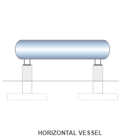
- Horizontal Vessel Equipment
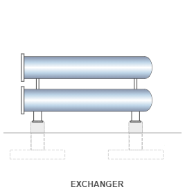
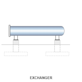
- Horizontal Heat Exchanger (Single or Double Heat Exchanger / Stacked Heat Exchanger one above the another)
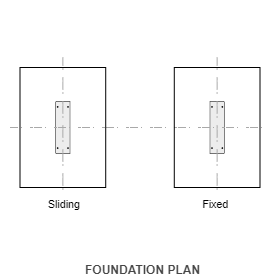
Horizontal Vessel is a pressure vessel used to hold gas or liquid. Any one end of this vessel will have a fixed type
saddle and another end is with sliding type saddle.
Heat Exchanger is a shell and tube type horizontal equipment to exchange heat between two or more fluids.
The shell end will have a fixed type saddle and the channel end is with sliding type saddle.
Features
- This program needs a very limited input information from the user at any stage of the Project Phases (Proposal or FEED or Detail Engineering or EPC) to design foundations.
- Option for intermediate support (Sliding Mid) New
- The horizontal equipment foundation analysis and design can be done with the following options,
- Combined footing
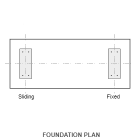
- Isolated footing (Typical and Non typical) for fixed and sliding Mid/End supports
- The pedestals design is having option to design typical for both fixed and sliding mid/end supports or non-typical for each support type.
- The user input loads are guided by predefined input field as defined in User Interface Input with a recommendation for eccentric loads and moments as recommended by PIP.
- The total equipment load inputs are automatically transferred to fixed / sliding end supports as applicable by program based on load distribution as defined by the user.
- Wind and Seismic load calculation are calculated automatically by the program based on selection of country code for the design.
- Wind and Seismic loads calculation are also entered manually based on input by the User/Vendor option.
- Wind and Seismic loads can be used by Program simultaneously using by User/Vendor option as well by Program Option to compare both values and design without any compromise on the quality of input from the Vendors.
- Automatic multiple Load Combination are generated by program based on selection of country code for the design in addition to user defined load combinations.
- The user provided loads in empty, operating and test can be increased or decreased in terms of percentage as per user engineering judgement. Based on user input for increase or decrease in vertical (empty/operating/test) loads, additional load combinations are added in addition to basic load combinations. The program performs analysis and design calculation for basic load using basic load combinations and increase or decrease vertical loads using additional load combinations. Hence, the critical load combination is defined by comparing all load combinations without any ambiguity/confusion.
- A provision to specify minimum soil cover is available in case full soil cover cannot be guaranteed due to any expected adjacent excavations.
- Ground water table buoyancy effect on stability and design is available.
- Passive resistance on Pad and Pedestal are included in the calculation as options based on user choice.
- User can specify the allowable stability factors and increase or decrease in SBC (Test, Wind and Seismic).
- Loads and Load Combinations can be easily imported from Microsoft Excel Through clipboard facility.
- Crack width for pad at top and bottom is checked as an option for each serviceability combinations.
- Facility to check the anchorage capacity and interaction ratio for anchor bolts.
- Comprehensive design report and summary results. A step by step design calculation report eliminates any requirements for additional validation of the calculation.
Design Considerations
- Loads on fixed and sliding end pedestal are auto calculated based on the distribution percentage on fixed and sliding end.
- Self-weight of soil, pad and pedestal is considered by program. Dead Load Factor is used as self-weight factor
- Unfactored and factored loads on each pedestal location is calculated based on the SLS and ULS combinations.
- Stability factors (overturning, sliding, uplift and SBC) for each load combination are compared with allowable factors (generated by program).
- Pad section crack width is checked for service moment at critical location of pad on two faces (top and bottom) in both directions.
- Moment capacity adequacy is checked for both directions and top and bottom with critical ULS combination.
- One-way shear (Wide Beam Shear) is computed at "d" distance form pedestal face of each location in both directions. Critical ULS combination and location reported.
- Two-way shear (punching shear) is checked at column face with maximum allowable shear stress and at "1.5d" distance from pedestal face against concrete shear capacity.
- For both pedestals, axial load and biaxial moment capacity compared with design load and moment of each ULS combinations.
- Pedestal tie spacing is computed based on the total lateral force over the section compared with maximum allowable spacing.
National Standards Available
British Standard
Euro Standard
- National Annex of several countries such as Europe (Recommended), UK, Finland, Ireland, Malaysia, Norway, Singapore, Sweden are considered.
- Additionally, an option is provided to define the coefficients directly by the user.
American Standard
- The calculation allows the user to design the section in both imperial and metric units.
References
- BS 8110-1:1997 - Structural use of concrete - Part 1: Code of practice for design and construction.
- EN 1992-1-1:2004 - Design of concrete structures - Part 1-1: General rules and rules for buildings.
- ACI 318-14 - Building Code Requirements for Structural Concrete.
- ACI-224R-01 - Control of Cracking in Concrete Structures.
- PIP-STE03360 - Heat Exchanger and Horizontal Vessel Foundation Design Guide - Process Industry Practices Structural.
Revision
- Ver 2.1 - Intermediate Saddle Support Option
- Ver 2.0 - Pile Support Option
- Ver 1.0 - Original version
|
|
Download Sample Report |