Help Topics
ECHORVES - Horizontal Vessel / Equipment Foundation Design
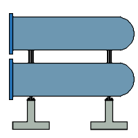
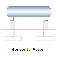
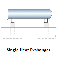
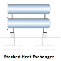
ECHORVES application is used to design the foundation for a Horizontal Vessel Equipment or Single Heat Exchanger or a Stacked Heat Exchanger (maximum of two heat exchangers one above the another in the vertical direction) Equipment using very limited available information at any stage of the Project Phases (Proposal or FEED or Detail Engineering or EPC Phases of the Project).
ECPlus applications are designed as a wizard type which is a step by step guided input procedure. If you are new to EC Plus applications, click here for general guidance to use all EC Plus applications.
ECHORVES is used to design all types of Horizontal Equipment Foundations. The common types of the horizontal equipment are covered under the following two categories.
1. Horizontal Vessel Equipment
2. Horizontal Heat Exchanger (Single Heat Exchanger or Stacked Heat Exchanger)
Prerequisites: The user is expected to have a basic understanding of equipment foundation design concepts. However, the program is very user friendly even for civil engineering graduate trainees.
The minimum input data required to use this application are as follows:
- ❶ Soil data such as Safe Bearing Capacity, Density of Soil, Angle of Internal Friction, Co- efficient of internal friction between bottom of foundation/soil, Ground Water Table and other soil parameters, reinforced concrete properties, Allowable Stability Safety Factors, etc., which are to be defined in the settings by the User
- ❷ Design Options
- ❸ Equipment Geometric Data
- ❹ Pedestal and footing / pad information
- ❺ Design parameters for environmental design loads of such as wind and seismic, as per country code requirements
 Following sections are presented with various input pages of ECHORVES application with descriptions:
 Design Options
This page allows the user to select the foundation support type, equipment type, design standard and unit.
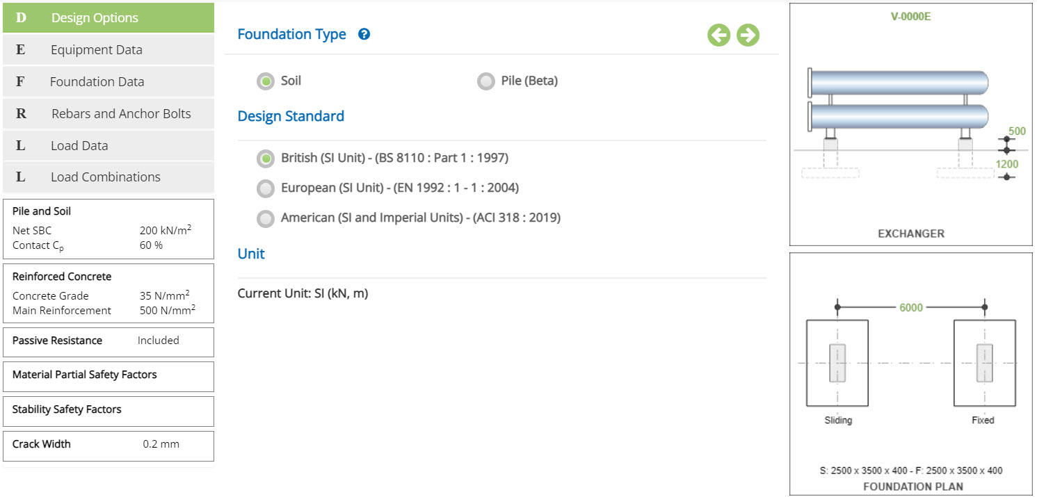 Foundation Type
Select if the foundation is supported on Soil or Pile
The user-friendly radio button option is selected by the user according to the foundation type. The application is having option to select the foundation type as on Soil Supported or Pile-Supported. Presently, only soil supported option is available. Based on selection, the input field as applicable to the foundation type is enabled for the user to exercise information as required for design the foundation.
Pile option is now available as beta version.
Design StandardSelect the National Standard for the design. Available Standards: ☉British, ☉European and ☉ American.
Unit
It displays the active unit. The unit Change button is displayed when ☉American Standard is selected.
British and European Standards cannot be selected when Imperial unit is active.
Change
Click this button to open the unit change pop-up dialog.
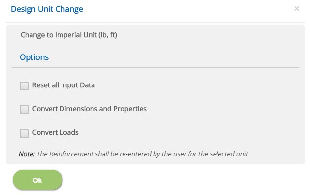
☐ Reset all Input Data
This option will reset the input data from the current unit to change (new) unit under American Standard option. This option is recommended if the job is new and no input data has been entered yet.
☐ Convert Dimensions and Properties
This option allows to convert all the previously entered input data except Load data to the new unit.
☐ Convert Loads
This option allows to convert previously entered load data to the new unit.
Note: Both Convert Dimensions and Properties and Convert Loads options can be used simultaneously to convert all the previously entered input values to the new unit.
- Note: While the program attempts to reasonably convert the rebar sizes equivalent to the new unit, the user should verify the reinforcement pages to ensure that the conversion has been applied as expected.
Equipment Data
This page allows the user to enter the equipment data as per equipment type selected in the Design Options.
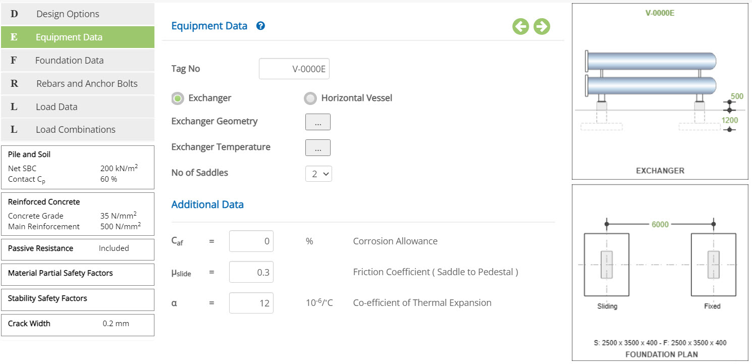 Tag No
Enter the tag number of the equipment based on equipment data sheet.
Equipment TypeSelect if the type of equipment used is an Exchanger or Horizontal Vessel
☉Exchanger: Select this option to design the foundation for a single exchanger or a stacked exchanger.
Heat Exchanger is a shell and tube type horizontal equipment used for cooling the hot liquids with cooling water by the surface contact between two mediums. The shell end will have a fixed type saddle and channel end is with sliding type saddle.
☉Horizontal Vessel: Select this option to design the foundation for a horizontal vessel.
Horizontal Vessel is a pressure vessel used for storage of liquids. Any one end of this vessel will have a fixed type saddle and another end is with sliding type saddle.
No of Saddles▽ 2: Select this option to add two number of saddles as Fixed End and Sliding End.
▽ 3: Select this option to add three number of saddles as Fixed End, Sliding Mid and Sliding End.
Enter the corrosion allowance factor in % for the equipment based on input. Normally, this input is in “mm” or “inches” based on unit used in the project which is to be converted as a percentage (%) with respect to original thickness of shell.
Corrosion Allowance Factor (Caf) = {(Original Thickness – Corrosion Allowance) / (Original Thickness)} x 100.
↔ Range: 0 to 90 %
- Note: What is the meaning of a Range used in the user manual? Range is a predefined limit set in the application to ensure user to enter values within these limits by providing a warning to the user. This will avoid user to enter any illogical values by mistake which may crash the program or abrupt end of the calculation. In case user wants to change these limits, the same may be communicated to EC PLUS Technical Support Team using Contact Us.
Enter the friction coefficient based on type of materials used between bottom of equipment saddle and top surface of the pedestal.
A sliding plate is generally used between the surfaces to reduce the transfer of longitudinal shear forces to the pedestals due to thermal forces, bundle pull forces, wind and/or earthquake forces.
ECHORVES estimates the longitudinal forces based on statics due to applied external loads as listed above. If user provides a coefficient of friction value greater than zero, the program calculates the force required to overcome the friction developed at the sliding surfaces. If this friction force is less than the longitudinal forces, the friction force is considered for the design of the pedestal at sliding end support and the higher of friction or remaining forces is used for the pedestal at fixed end support. If the longitudinal force is less than the friction force, the longitudinal force is considered for the design of the pedestal at fixed and sliding ends.
- Note: If user provides a coefficient of friction value as equal to zero, the full longitudinal shear force value is applied on the fixed end pedestals for the design.
The following general guide lines shall be used by the user for slide plates.
Slide plate may not be required for small, lightly loaded exchangers or vessels. However, in case of heavy exchangers / vessels or exchangers with large thermal growth will be provided with low- friction Teflon slide plates.
The exchangers with bundle pull may be provided with steel slide plates instead of Teflon plates for more economical foundation design of system.
The coefficient of friction of slide plates shall vary based on slide plate material, temperature and pressure. Hence, the value shall be obtained from the catalogue or manufacturer. In the absence of information, the following values may be used for reference.
| No slide plate. The saddle is directly on the concrete | 0.6 |
| Slide plate using steel | 0.4 |
| Slide plate using materials like Teflon, etc., | 0.05 to 0.20 |
↔ Range: 0 to 1
Co-efficient of Thermal Expansion - αEnter the co-efficient of thermal expansion for the equipment based on material type used for the manufacturing of the equipment as per input data.
↔ Range: 0.1 to 20 /°C (0.1 to 20 /°F)
The co-efficient of thermal expansion for steel material is 12 x 10-6 / degree (6.67 x 10⁻⁶ / Fahrenheit) is already stored as a default in the ECHORVES Program. The value is to be changed by the user based on equipment material.
Single Exchanger Geometry
Click the Exchanger Geometry button to open the exchanger geometry change pop-up dialog and select the No. of Exchangers (Ne) as “Single” using pull down menu option.
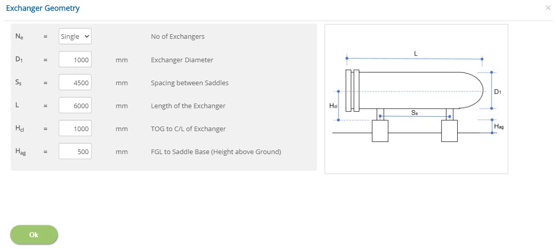 No of Exchangers
As explained above, select whether to design with one or two exchangers using pull down menu.
Exchanger Diameter - D1Enter the diameter of the exchanger (D1) as per input. D1 indicates first exchanger diameter. The 2nd exchanger diameter is not applicable due to single exchanger. This information is used by the program to represent in the picture as per scale and also used for a cross line validation during wind calculation by the program.
↔ Range: 200 to 10000 mm (8 to 400 inches)
Enter the spacing between the saddles (Ss) as per input. This information is used to calculate thermal growth of the equipment. In addition, based on Isolated Foundation size and the gap available between saddle supports is less than 1000mm, a recommendation is advised by the program to proceed for Combined Foundation instead of Isolated Foundation.
↔ Range: 500 to 50000 mm (20 to 2000 inches)
Enter the length of the exchanger (L) based on input. This information is used by the program to represent in the picture as per scale and also used for a cross line validation during wind calculation by the program.
↔ Range: 1000 to 60000 mm (40 to 2400 inches)
Enter the height to centre line of exchanger dimension (Hcl) from the top of the grout (TOG). This input is used to transfer program calculated shear forces due to Wind / Seismic / Bundle Pull to support level as a pull / push forces in the longitudinal direction and as a moment in the transverse direction.
↔ Range: 100 to 10000 mm (4 to 400 inches)
Enter the height of the pedestal above ground (Hag). This is the height to saddle base / top of the pedestal grout from the high point of paving (HPP) or finished ground level (FGL).
↔ Range: 100 to 10000 mm (4 to 400 inches)
Double Exchanger Geometry
Click the Exchanger Geometry button to open the exchanger geometry change pop-up dialog and select the No. of Exchangers (Ne) as “Double” using pull down menu option.
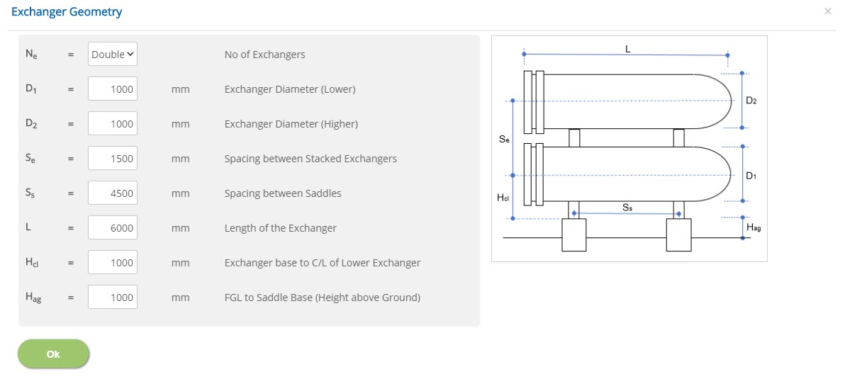 No of Exchangers
As explained above, select whether to design with one or two exchangers using pull down menu.
Exchanger Diameter (Lower) - D1Enter the diameter of the lower exchanger (D1) as per input. D1 indicates first exchanger diameter. This information is used by the program to represent in the picture as per scale and also used for a cross line validation during wind calculation by the program.
↔ Range: 200 to 10000 mm (8 to 400 inches)
Enter the diameter of the higher exchanger (D2) as per input. D2 indicates second exchanger diameter. This information is used by the program to represent in the picture as per scale and also used for a cross line validation during wind calculation by the program.
↔ Range: 200 to 10000 mm (8 to 400 inches)
Enter the spacing height between the two staked exchangers (Sv) in the vertical direction. This is the distance between centre line of the lower exchanger and the higher exchanger.
↔ Range: 500 to 10000 mm (20 to 400 inches)
Enter the spacing between the saddles (Ss) as per input. This information is used to calculate thermal growth of the equipment. In addition, based on Isolated Foundation size and the gap available between saddle supports is less than 1000mm, a recommendation is advised by the program to proceed for Combined Foundation instead of Isolated Foundation.
↔ Range: 500 to 50000 mm (20 to 2000 inches)
Enter the length of the exchanger (L) based on input. This information is used by the program to represent in the picture as per scale and also used for a cross line validation during wind calculation by the program.
↔ Range: 1000 to 60000 mm (40 to 2400 inches)
Enter the height to centre line of the lower exchanger dimension (Hcl) from the top of the grout (TOG). This input is used to transfer program calculated shear forces due to Wind / Seismic / Bundle Pull to support level as a pull / push forces in the longitudinal direction and as a moment in the transverse direction.
↔ Range: 100 to 10000 mm (4 to 400 inches)
Enter the height of the pedestal above ground (Hag). This is the height to saddle base / top of the pedestal grout from the high point of paving (HPP) or finished ground level (FGL).
↔ Range: 100 to 10000 mm (4 to 400 inches)
Vessel Geometry
Click the Vessel Geometry button to open the vessel geometry change pop-up dialog to provide input.
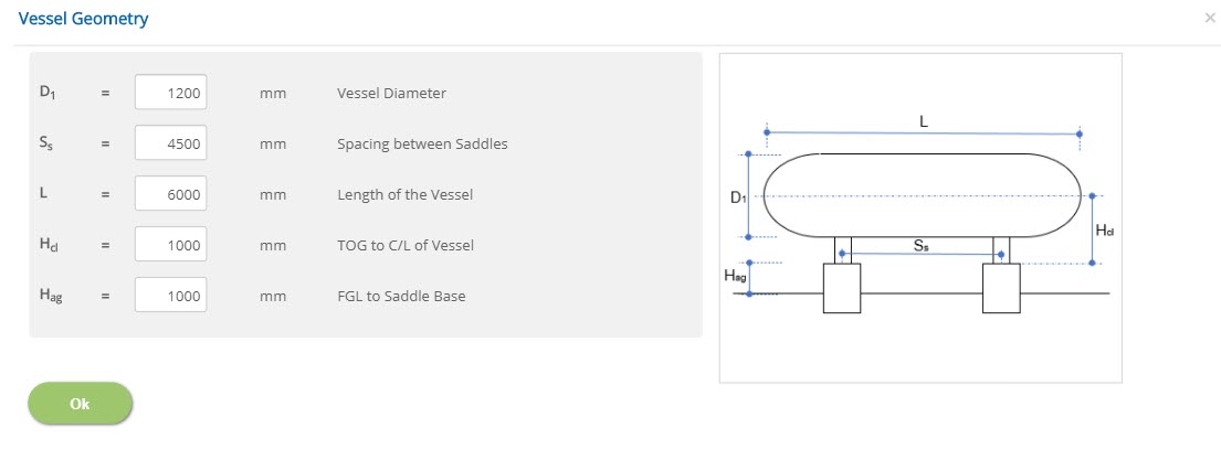 Vessel Diameter - D1
Enter the diameter of the horizontal vessel (D1) as per input. This information is used by the program to represent in the picture as per scale and also used for a cross line validation during wind calculation by the program.
↔ Range: 200 to 10000 mm (8s to 400 inches)
Enter the spacing between the saddles (Ss) as per input. This information is used to calculate thermal growth of the equipment. In addition, based on Isolated Foundation size and the gap available between saddle supports is less than 1000mm, a recommendation is advised by the program to proceed for Combined Foundation instead of Isolated Foundation.
↔ Range: 500 to 50000 mm (20 to 2000 inches)
Enter the length of the horizontal vessel (L) based on input. This information is used by the program to represent in the picture as per scale and also used for a cross line validation during wind calculation by the program.
↔ Range: 1000 to 60000 mm (40 to 2400 inches)
Enter the height to centre line of horizontal vessel dimension (Hcl) from the top of the grout (TOG). This input is used to transfer program calculated shear forces due to Wind/Seismic/Bundle Pull to support level as a pull / push forces in the longitudinal direction and as a moment in the transverse direction.
↔ Range: 100 to 10000 mm (4 to 400 inches)
Enter the height of the pedestal above ground (Hag). This is the height to saddle base/top of the pedestal grout from the high point of paving (HPP) or finished ground level (FGL).
↔ Range: 100 to 10000 mm (4 to 400 inches)
Exchanger / Vessel Temperature
This page allows to enter the exchanger / vessel temperature details.
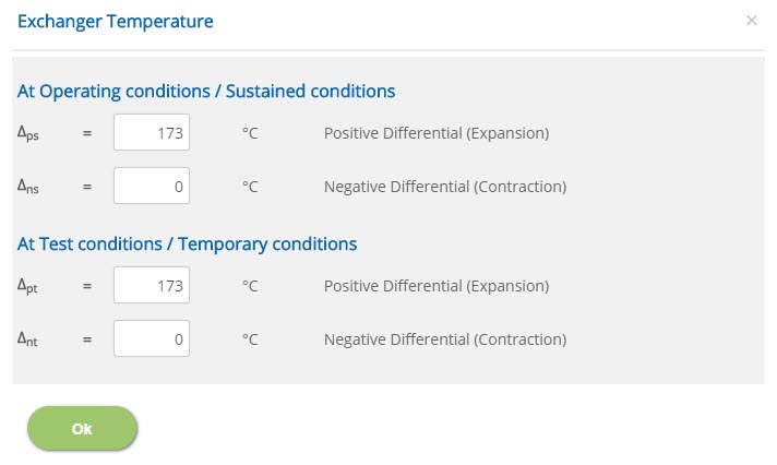 Positive Differential (Expansion) Temperature at Operating / Sustained Conditions - Δps
The difference between equipment maximum operating/design temperature and installed temperature is calculated by the user and the average temperature is entered as a positive differential temperature to calculate thermal expansion of the equipment at operating / sustained conditions.
↔ Range: 0 to 500 ◦C
The difference between equipment minimum operating/design temperature and installed temperature is calculated by the user and the average temperature is entered as a negative differential temperature to calculate thermal contraction of the equipment at operating / sustained conditions.
↔ Range: 0 to 500 ◦C
The difference between equipment maximum exposure to atmospheric/ambient temperature and installed temperature is calculated by the user and the average temperature is entered as a positive differential temperature to calculate thermal expansion of the equipment at temporary conditions or stat-up/shut-down conditions.
↔ Range: 0 to 500 ◦C
Negative Differential (Contraction) Temperature at Test / Temporary conditions - Δnt
The difference between equipment minimum exposure to atmospheric/ambient temperature and installed temperature is calculated by the user and the average temperature is entered as a negative differential temperature to calculate thermal contraction of the equipment at temporary conditions or stat-up/shut-down conditions.
↔ Range: 0 to 500 ◦C
As per clause 4.1.7.4C of PIP STC01015-2017, an additional 20degree Celsius (30degree Fahrenheit) minimum shall be added to the maximum atmospheric / ambient temperature of any steel directly exposed to sunlight without any insulation or shade etc., or based on engineering judgement.
Foundation Data
This page allows the user to enter the foundation data to design as a combined or isolated type foundation. Based on selected foundation type, pedestal, footing information and soil cover in case of any reduction as stipulated in the project.
Foundation Type
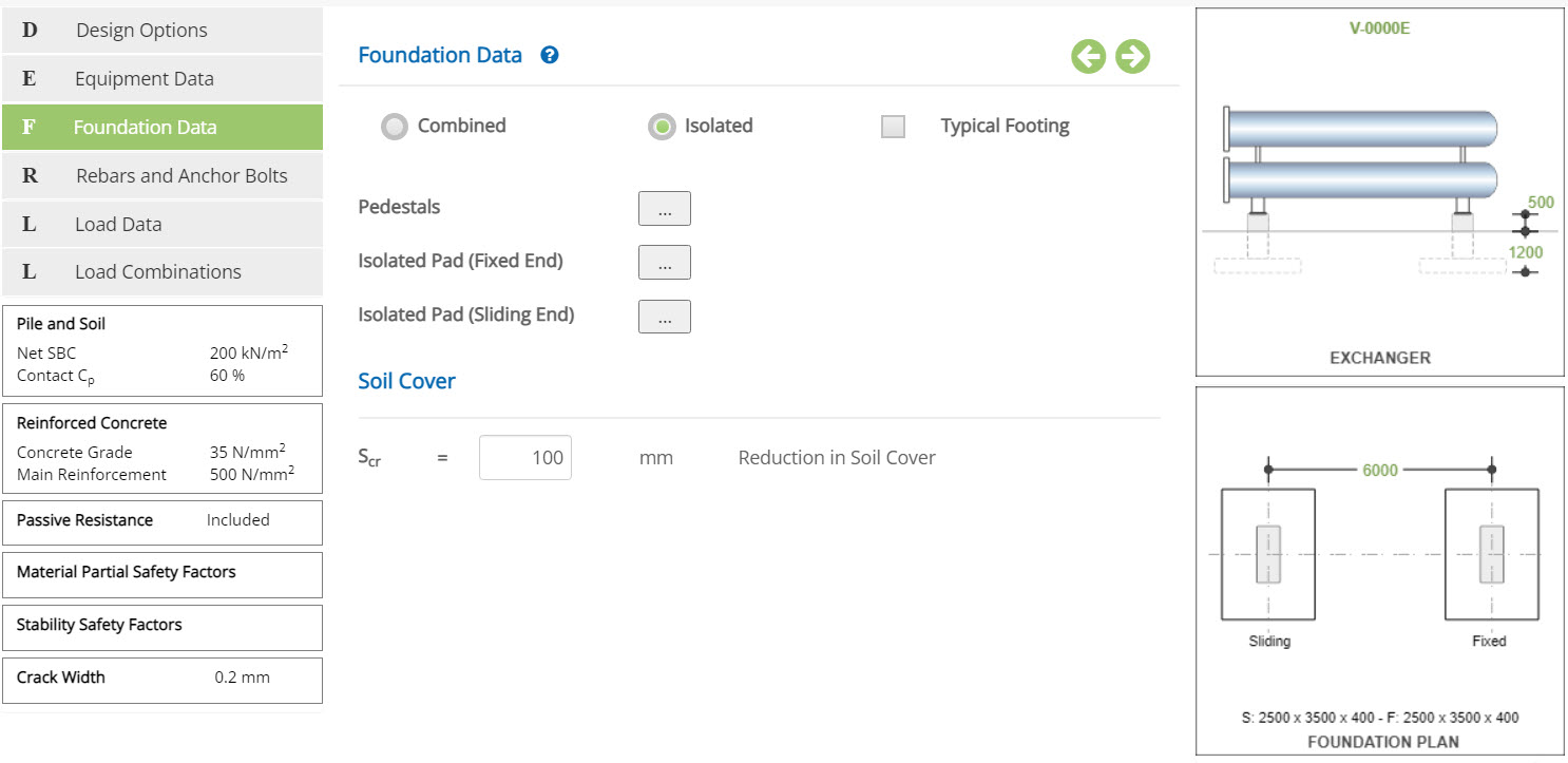
Select whether to use Combined or Isolated.
The user may judge and select the option based on spacing between fixed and sliding ends. In addition, based on Isolated Foundation size an d the gap available between saddle supports is less than 1000mm, a recommendation is advised by the program to proceed for Combined Foundation instead of Isolated Foundation.
The Isolated foundation design is having option to select typical or non-typical footing for fixed/sliding ends. In general, both pedestals are designed with same size and detailing. However, if the user prefers to design independently according to the forces subjected to the pedestals, an option is provided for the user to exercise.
☐ Typical Footing for Fixed / Sliding Ends:
Check this option to use typical footing for both fixed and sliding ends. As similar to pedestals, the footings are also designed with same size and detailed. However, if the user prefers to design independently according to the forces subjected to the pedestals/footings, an option is provided for the user to exercise.
The reduction in soil cover from the high point of paving (HPP) or finished ground level (FGL). is provided as an input by the user as per requirements or user choice to account in the design. In the absence of information, the default value of zero for no reduction in soil cover is considered.
↔ Range: 0 to 5000 mm (0 to 200 inches)
Pedestal Dimensions
Click this button to open the pedestal dimension pop-up dialog. The pedestal design is having option to select typical or non-typical pedestal design for fixed / sliding ends.
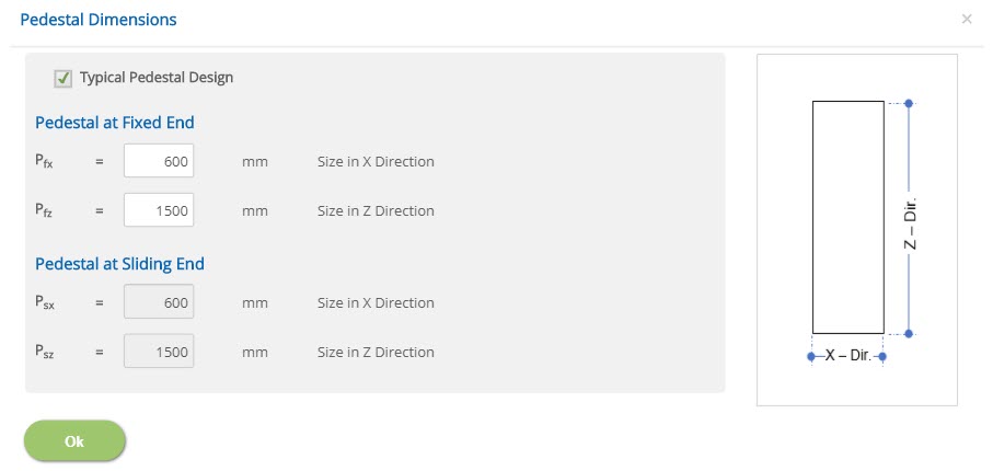
☐ Typical Pedestal Design:
Select this option to use typical pedestal design for both fixed and sliding end.
Pedestal at Fixed End
Size in X Direction - PfxEnter the size of pedestal in X direction at fixed end (Pfx). This dimension is decided by the user based on equipment fixed end saddle width which is parallel to the longitudinal direction of the heat exchanger or horizontal vessel. The minimum size shall be 250mm (10 inches) or slide plate width + 100mm (4 inches) or as required to accommodate anchor bolt edge distance from the bolt location.
↔ Range: 200 to 3000 mm (8 to 120 inches)
Enter the size of pedestal in Z direction at fixed end (Pfz). This dimension is decided by the user based on fixed end saddle length which is perpendicular to the longitudinal direction of the heat exchanger or horizontal vessel. The minimum size shall be slide plate depth + 100mm (4 inches) or as required to accommodate anchor bolt edge distance from the bolt location.
↔ Range: 200 to 20000 mm (8 to 800 inches)
Pedestal at Sliding End
Size in X Direction - PsxEnter the size of pedestal in X direction at sliding end. This dimension is decided by the user based on equipment sliding end saddle width which is parallel to the longitudinal direction of the heat exchanger or horizontal vessel. The minimum size shall be 250mm (10 inches) or slide plate width + 100mm (4 inches) or as required to accommodate anchor bolt edge distance from the bolt location.
↔ Range: 200 to 3000 mm (8 to 120 inches)
Enter the size of pedestal in Z direction at sliding end. This dimension is decided by the user based on sliding end saddle length which is perpendicular to the longitudinal direction of the heat exchanger or horizontal vessel. The minimum size shall be slide plate depth + 100mm (4 inches) or as required to accommodate anchor bolt edge distance from the bolt location.
↔ Range: 200 to 20000 mm (8 to 800 inches)
Isolated Footing - Fixed / Sliding Mid / Sliding End
Click this button to open the isolated footing at fixed or sliding end pop-up dialog. As per ECHORVES, the position of Sliding End is always at left side of the equipment and Fixed End is always at right side of the equipment. Hence, the user must provide input according to these criteria.
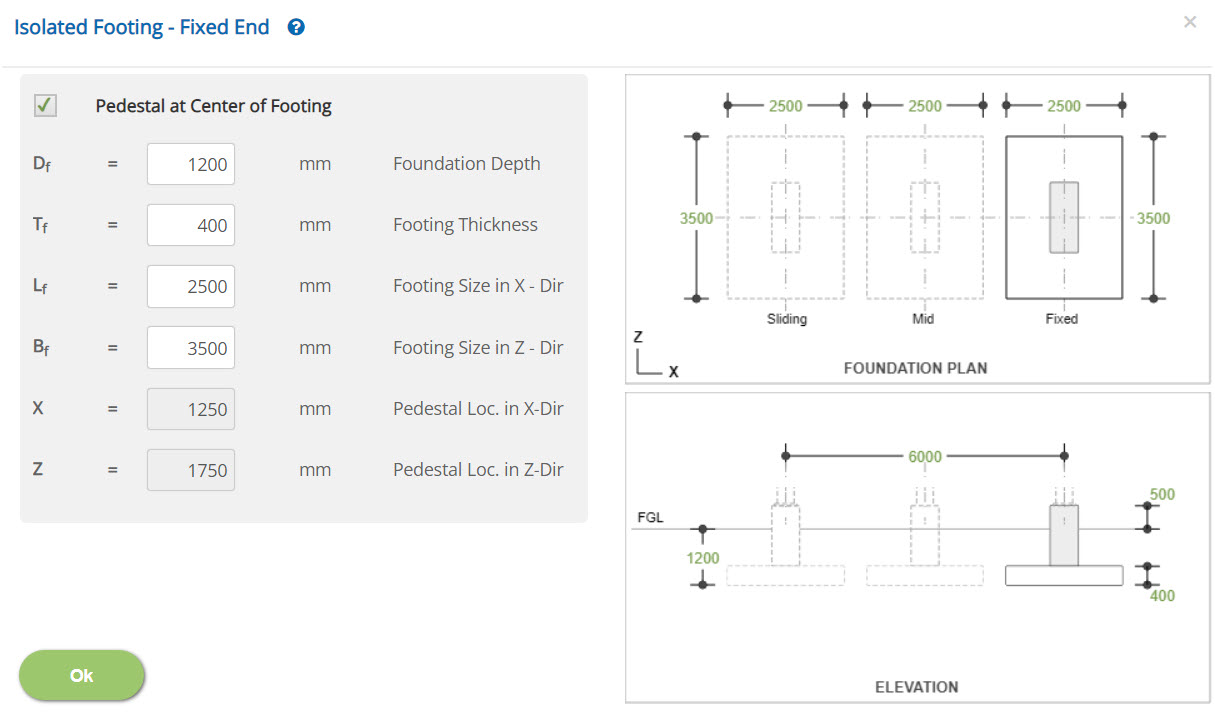
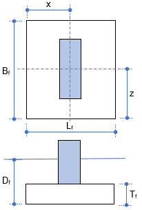
☐ Pedestal at Center of Footing:
Select this option to center the pedestal with respect to the footing. This facility ensures the position of the pedestal at center with respect to the footing. The selection of this option will disable the position of pedestal location in X and Z directions.
Enter the depth of the foundation (Df) with respect to High Point of Paving high point of paving (HPP) or finished ground level (FGL).
↔ Range: 0 to 5000 mm (0 to 200 inches)
Enter the thickness of the footing (Tf) based on minimum footing thickness criteria as stipulated in the project design basis.
↔ Range: 100 to 10000 mm (4 to 400 inches)
Enter the length of the footing (Lf). The length of footing dimension is always parallel to the longitudinal direction of the heat exchanger or horizontal vessel.
↔ Range: 300 to 100000 mm (12 to 4000 inches)
Enter the breadth of the footing (Bf). The breadth of footing dimension is always perpendicular to the longitudinal direction of the heat exchanger or horizontal vessel.
↔ Range: 300 to 100000 mm (12 to 4000 inches)
Enter the location of the pedestal in X direction (X). This option is enabled to the user only if the pedestal at centre of footing option is not selected. The centre of the pedestal is positioned based on left bottom of the respective footing as an origin.
↔ Range: 0 to 100000 mm (0 to 4000 inches)
Enter the location of the pedestal in Z direction (Z). This option is enabled to the user only if the pedestal at centre of footing option is not selected. The centre of the pedestal is positioned based on left bottom of the respective footing as an origin.
↔ Range: 0 to 100000 mm (0 to 4000 inches)
Combined Footing
Click this button to open the combined footing pop-up dialog. As per ECHORVES, the position of Sliding End is always at left side of the equipment and Fixed End is always at right side of the equipment. Hence, the user must provide input according to these criteria.
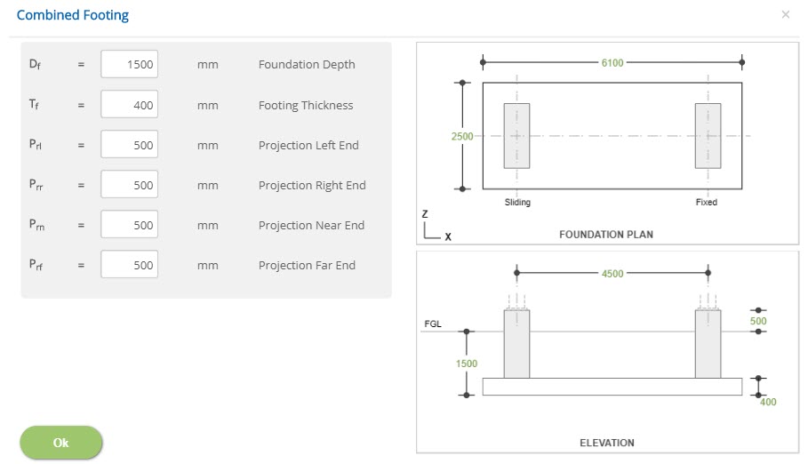
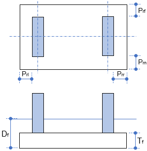 Foundation Depth - Df
Enter the depth of the foundation (Df) with respect to High Point of Paving high point of paving (HPP) or finished ground level (FGL).
↔ Range: 0 to 5000 mm (0 to 200 inches)
Enter the thickness of the footing (Tf) based on minimum footing thickness criteria as stipulated in the project design basis.
↔ Range: 100 to 10000 mm (4 to 400 inches)
The length of footing dimension is always parallel to the longitudinal direction of the heat exchanger or horizontal vessel.
↔ Range: 300 to 100000 mm (12 to 4000 inches)
The breadth of footing dimension is always perpendicular to the longitudinal direction of the heat exchanger or horizontal vessel.
Projection Left End - PrlEnter the projection at the left end. The extension/projection is calculated from the left edge of the sliding end pedestal. This is the clear distance between left end of the footing from the left edge of the sliding end pedestal.
↔ Range: 0 to 20000 mm (0 to 800 inches)
Enter the projection at right end. The extension/projection is calculated from the right edge of the fixed end pedestal. This is the clear distance between right end of the footing from the right edge of the fixed end pedestal.
↔ Range: 0 to 20000 mm (0 to 800 inches)
Projection Near End - Prn
Enter the projection at near end. The extension/projection is calculated from the bottom edge of the pedestal. This is the clear distance between bottom end of the footing from the bottom edge of the fixed/sliding end pedestals.
↔ Range: 0 to 20000 mm (0 to 800 inches)
Enter the projection at far end. The extension/projection is calculated from the top edge of the pedestal. This is the clear distance between top end of the footing from the top edge of the fixed/sliding end pedestals.
↔ Range: 0 to 20000 mm (0 to 800 inches)
Rebars and Anchor Bolts
This page allows the user to enter reinforcement and anchor bolt details.
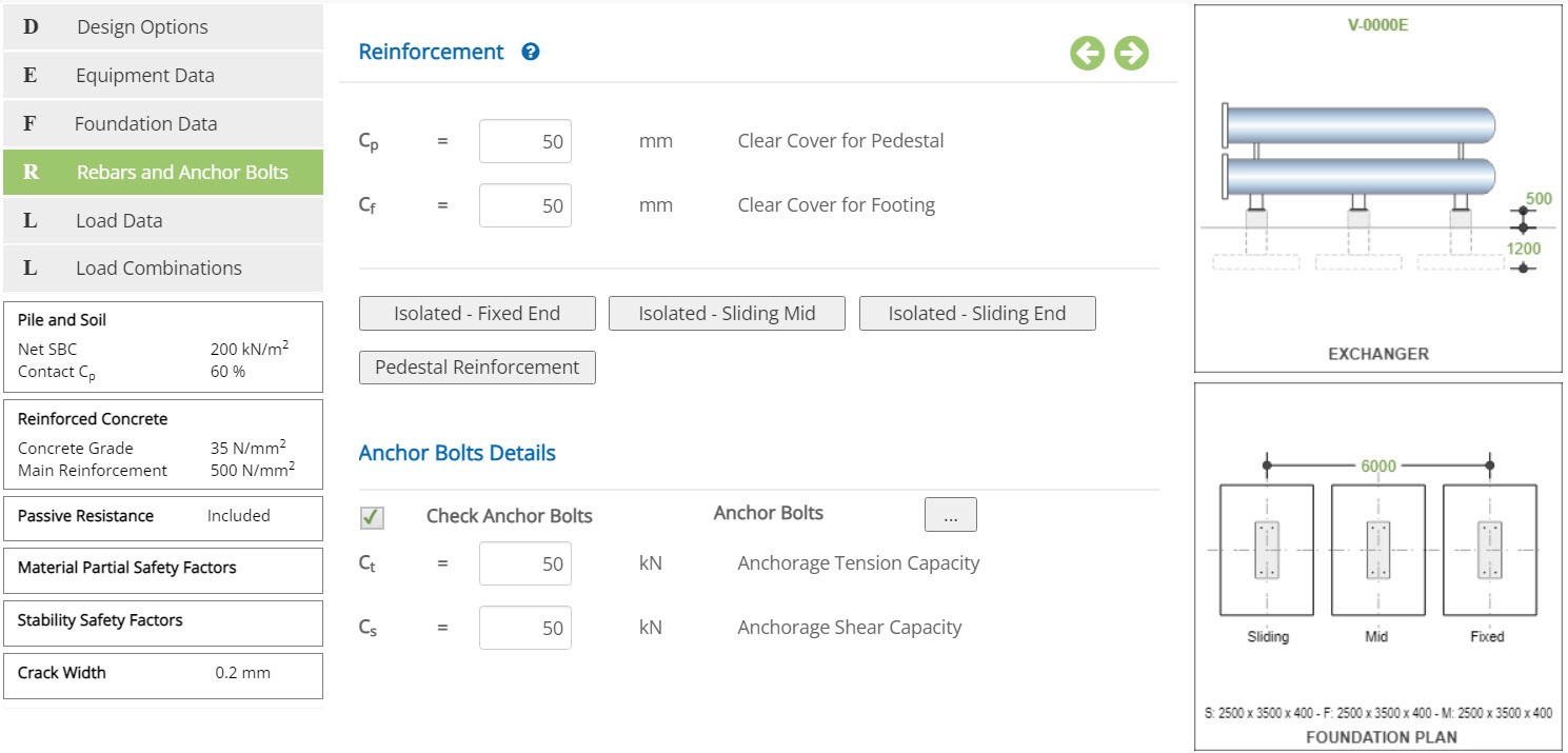 Clear Cover for Pedestal - Cp
Enter the clear cover for pedestal (Cp) reinforcements as per input.
↔ Range: 15 to 150 mm (0.5 to 6 inches)
Enter the clear cover for footing (Cf) reinforcements as per input.
↔ Range: 15 to 150 mm (0.5 to 6 inches)
Combined Footing
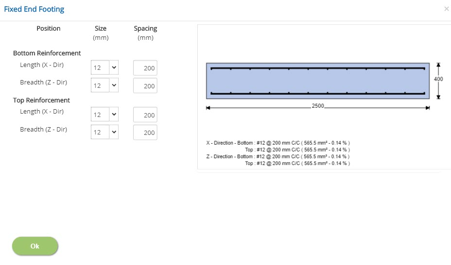
Click this button to open the reinforcement for combined footing pop-up dialog to provide reinforcements input in X and Z directions at top and bottom of the footing. The reinforcement diameter and spacing are supplied as input which is validated by the program against actual capacity with required capacity. The total area of the reinforcements with percentage (%) in each direction is shown below the reinforcement diagram for user quick reference. This is useful for the user to take any decision to modify already provided data for reinforcements. In the case of the combined footing, the top and bottom longitudinal reinforcements in the X-direction are main tension reinforcements which are to be satisfied for the minimum % tension reinforcement for slab/footing as applicable to the selected country code. The transverse reinforcements in the z direction are secondary reinforcements which are to be satisfied for the minimum % of temperature reinforcement for slab / footing as to the selected country code. However, the user has option to provide input based on analysis results, engineering judgement to satisfy any code requirements.
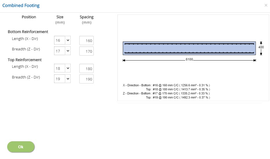 Size (mm or # No.)
Select the size of length and breadth reinforcement for both bottom and top layers.
↔ Range: 4 to 60 mm
Spacing (mm or in)
Enter the spacing of length and breadth reinforcement for both bottom and top layers.
↔ Range: 20 to 450 mm (1 to 18 inches)
Fixed / Sliding Mid / Sliding End Pedestal - Reinforcement
Click this button to open the reinforcement for fixed / sliding end pedestal to provide vertical reinforcements input in X and Z directions. The reinforcement diameter and spacing are supplied as input which will position the reinforcements in all face of the pedestal. Based on these reinforcements, the program calculates actual capacity to compare with required capacity. The total area of the reinforcements with percentage (%) is shown below the reinforcement diagram for user reference. This helps user to take any decision to modify already provided data for reinforcements.
In addition, provision is available to enter ties diameter, spacing and number of ties as required
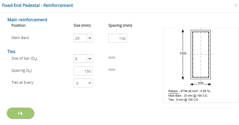 Size
SizeEnter the size of main reinforcement for fixed / sliding end pedestal.
↔ Range: 4 to 60 mm
Enter the spacing of main reinforcement for fixed / sliding end pedestal.
↔ Range: 20 to 450 mm (1 to 18 inches)
Enter the size of bar for ties of fixed / sliding end pedestal reinforcement.
↔ Range: 4 to 60 mm
Spacing - Ss
Enter the spacing for ties of fixed / sliding end pedestal reinforcement.
↔ Range: 20 to 450 mm (1 to 18 inches)
Select to specify if intermediate ties are provided and for every or alternative vertical reinforcement. Select zero if no intermediate ties are provided.
Isolated Footing
Fixed End, Sliding Mid and Sliding End Footing Reinforcement
Click this button to open the reinforcement for isolated footing pop-up dialog. to provide reinforcements input in X and Z directions at top and bottom of the footing. The reinforcement diameter and spacing are supplied as input which is validated by the program against actual capacity with required capacity. The total area of the reinforcements with percentage (%) in each direction is shown below the reinforcement diagram for user quick reference. This is useful for the user to take any decision to modify already provided data for reinforcements. In the case of the isolated footing, the bottom reinforcements in the X-direction and z directions are main tension reinforcements which are to be satisfied for the minimum % tension reinforcement for slab/footing as applicable to the selected country code. The top reinforcements in the x and z directions are secondary reinforcements which are to be satisfied for the minimum % of temperature reinforcement for slab/footing as applicable to the selected country code. However, the user has option to provide input based on analysis results, engineering judgement to satisfy code requirements.
 Size
SizeSelect the size of length and breadth reinforcement for both bottom and top layers.
↔ Range: 4 to 60 mm
Spacing
Enter the spacing of length and breadth reinforcement for both bottom and top layers.
↔ Range: 20 to 450 mm (1 to 18 inches)
- Note: If 'Typical Footing for Fixed / Sliding Ends' is checked on Foundation Data, then typical reinforcement will be taken for both fixed and sliding ends.
Anchor Bolts
Click this button to open the anchor bolt details popup.
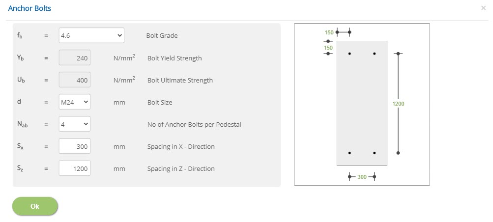 Bolt Grade - fb
Select the bolt grade (fb) as per input.
Bolt Yield Strength - YbThe default bolt material yield strength (Yb) is displayed as per selected grade. In case of user defined grade, this input field is enabled to enter bolt yield strength by the user.
↔ Range: 10 to 1000 N/mm2 (1.5 to 145 ksi)
The default bolt material ultimate strength (Ub) is displayed as per selected grade. In case of user defined grade, this input field is enabled to enter bolt ultimate strength by the user.
↔ Range: 10 to 1000 N/mm2 (1.5 to 145 ksi)
Select the bolt size (d) as per input.
No of Anchor Bolts per Pedestal - NabSelect the number of anchor bolts per pedestal (Nab) as per input. The user has option to select either 2 or 4 bolts per pedestal. However, user can enter any number of even bolts. If the number of bolts are more than 2, then the bolts will be placed with maximum 2 of columns per pedestal and as many as number of rows as required to accommodate all bolts.
Spacing in X - Direction - SxEnter the spacing in X direction (Sx). This input field is available only for 4 bolts and the dimension is to be as per input and the pedestal size may be modified based on edge distance requirements for anchor bolts. The input is provided in case of 2 bolts, the bolts are placed exactly at the middle of the pedestal.
↔ Range: 200 to 3000 mm (8 to 120 inches)
Enter the spacing in Z direction (Sz). This input field dimension is to be as per input and the pedestal size may be modified based on edge distance requirements for anchor bolts.
↔ Range: 200 to 20000 mm (8 to 800 inches)
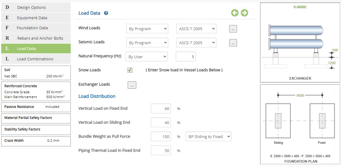
Load Data
This page allows user to enter load data for wind, seismic, vertical loads on the equipment. The wind and seismic loads are entered based on options (By User / Vendor, By Program, By Both or None) as per user choice. In addition, the user options are not limited to select any one country code or any one option. Example, the wind loads may be entered By User/Vendor option and at the same time the seismic load may be generated By Program or By Both option.
There are also provisions available to provide load distribution input for vertical loads, bundle pull loads and piping thermal loads as per configuration of equipment and based on user’s engineering judgements.
 Wind / Seismic Loads
▽ By User / Vendor: Select this option to use wind / seismic loads By User / Vendor. If the information is readily available with user from vendor or any other source, the User / Vendor option is selected. In this case, the actual wind/seismic loads are to be entered under Exchanger Loads or Vessel Loads as applicable.
▽ By Program: Select this option to calculate wind/seismic loads automatically by the program. Use loads by program. The required parameters to calculate automatically by the program are to be entered as per selected country code.
▽ By Both: Select this option to use loads by both user / vendor and program. In this option, the user is provided with both options to enter input. The program calculates and compares shear and moment values with user / vendor input. The maximum values are conservatively used for the calculation. However, based on comparison of user input and program calculated values, the user may take any appropriate decision either to proceed or comment any discrepancies to the vendor or inter-disciplines (source of input) to clarify / rectify before implementation.
▽ None: Select this option to run the calculation without wind or seismic loads as applicable.
▽ Code: Select the appropriate country code to use in case of by program option to calculate wind and seismic loads based on selection of applicable country code.
Wind Load by Program - BS 6399
Click this button to open the wind load by program popup based on British Standard BS 6399.
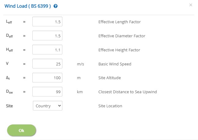 Effective Length Factor - Leff
Enter the effective length (Leff),factor.
↔ Range: 0.5 to 3
Enter the effective diameter (Deff),factor.
↔ Range: 0.5 to 3
| Vessel Diameter (m) | Increase Factor |
| 0.5 - 1.0 | 1.60 |
| 1.0 - 1.5 | 1.37 |
| 1.5 - 2.0 | 1.28 |
| 2.0 - 2.5 | 1.20 |
| 2.5 and up | 1.18 |
| Spherical (any dia.) | 1.10 |
Effective Height Factor - Heff
Enter the effective height (Heff), factor.
↔ Range: 0.5 to 3
Enter the basic wind speed (V), as per design criteria as applicable to the country code. This value shall be carefully decided by the user based on customer input as applicable to the selected country code to avoid any mistake.
↔ Range: 10 to 500 m/s (30 to 1700 mph)
Enter the site altitude (Δs) based on available information with reference to Mean Sea Level (MSL).
↔ Range: 10 to 500 m (0 to 1700 ft)
Enter the closest distance to sea upwind (Dsw) based on available input.
↔ Range: 10 to 1000 km (6 to 700 miles)
Select the site location. The available options are Country and Town.
Wind Load by Program - EN 1991
Click this button to open the wind load by program popup based on Euro Standard BS EN 1991.
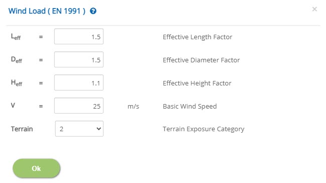 Effective Length Factor - Leff
Enter the effective length (Leff),factor.
↔ Range: 0.5 to 3
Enter the effective diameter (Deff),factor.
↔ Range: 0.5 to 3
For factors refer 'Standard Diameter Factors' table
Effective Height Factor - HeffEnter the effective height (Heff), factor.
↔ Range: 0.5 to 3
Enter the basic wind speed (V), as per design criteria as applicable to the country code. This value shall be carefully decided by the user based on customer input as applicable to the selected country code to avoid any mistake.
↔ Range: 10 to 500 m/s (30 to 1700 mph)
Select the terrain exposure category. The available options are 0, 1, 2, 3 & 4.
Wind Load by Program - ASCE 7
Click this button to open the wind load by program popup based on ASCE 7 - 2005, 2010 & 2016.
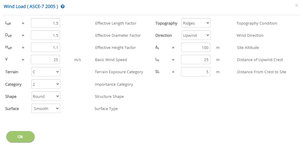 Effective Length Factor - Leff
Enter the effective length (Leff),factor.
↔ Range: 0.5 to 3
Enter the effective diameter (Deff),factor.
↔ Range: 0.5 to 3
For factors refer 'Standard Diameter Factors' table
Effective Height Factor - HeffEnter the effective height (Heff), factor.
↔ Range: 0.5 to 3
Enter the basic wind speed (V), as per design criteria as applicable to the country code. This value shall be carefully decided by the user based on customer input as applicable to the selected country code to avoid any mistake.
↔ Range: 10 to 500 m/s (30 to 1700 mph)
Select the terrain exposure category. The available options are B, C & D.
Importance CategorySelect the importance category. The available options are 0, 1, 2, 3 & 4.
Structure ShapeSelect the shape of the structure.
Surface TypeEnter the type of the surface. The available options are Moderate Smooth, Rough and Very Rough Surfaces.
Topography ConditionSelect the topography condition. The available options are Ridges, Escarpments, Hill & Cliff.
Wind DirectionSelect the wind direction. The available options are up wind and down wind.
Site Altitude - ΔsEnter the site altitude (Δs) based on available information with reference to Mean Sea Level (MSL).
↔ Range: 10 to 500 m (0 to 1700 ft)
Enter the distance of upwind crest.
↔ Range: 10 to 500 m (30 to 1700 ft)
Enter the distance from crest to site.
↔ Range: 1 to 500 m (3 to 1700 ft)
Seismic Load by Program (ASCE / IBC)
Click this button to open the seismic load by program popup based on ASCE-7 – 2005, 2010 & 2016 AND IBC 2018.
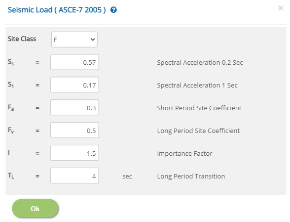 Site Class
Select the site class. The available options are A, B, C, D, E & F.
Spectral Acceleration 0.2 Sec - SsEnter the spectral acceleration at 0.2 second.
↔ Range: 0.2 to 10
Enter the spectral acceleration at 1 second.
↔ Range: 0.2 to 10
Enter the site coefficient for short period.
↔ Range: 0.1 to 5
Enter the spectral acceleration for long period.
↔ Range: 0.1 to 5
Importance Factor - I
Enter the importance factor.
↔ Range: 0.5 to 5
Enter the long period transition.
↔ Range: 0 to 60 sec
Natural Frequency (Hz)
▽ By Program: Select this option to calculate natural frequency automatically by the program.
▽ By User: Select this option to enter natural frequency manually at the corresponding input.
↔ Range: 0.5 to 100 Hz
☐ Snow Loads: Check this option to consider any loads due to snow on the equipment. This check box facility is kept outside before to enter exchanger/vessel load menu option in order to receive an input if applicable. If it is unchecked, the same shall not be editable by the user.
Exchanger Loads / Vessel Loads
Click this button to open the exchanger loads / vessel loads popup to enter input for all vertical loads and associated forces / moments. Loads are entered as force in X, Y, Z directions and moment about X (longitudinal axis) and Z (transverse axis) directions.
The standard sign conventions are followed as shown in load page.
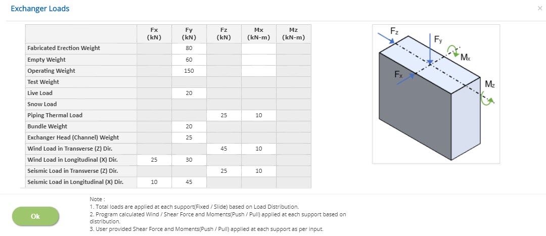
Fabricated Erection Weight - Dfa
Enter the fabricated erection weight (Dfa) for the exchanger/vessel. In case of stacked exchangers, the total fabricated weight of all exchangers is entered in the input field against Fy.
Applicable eccentric loading and moments during erection case shall be added in this row. A load of an additional 20% of applied fabricated erection weight for exchangers with diameters less than 600mm (24 inches) or 10% of applied fabricated erection weight for exchangers with diameters equal to or greater than 600mm (24 inches) and for vessels with irrespective of any diameters as a default value shall be considered as per clause 4.2.1.2 of PIP STE03360-2007.
This eccentricity moment value is entered in the input field against Mx.
↔ Range: -100000 to 100000
Empty Weight - De
Enter the empty weight (De) of the exchanger / vessel. In case of stacked exchangers, the total empty weight of all exchangers is entered in the input field against Fy. The empty weight of the exchanger / vessel excluding all attachments, trays, internals, bundle, insulation, fireproofing, agitators, piping, ladders, platforms, etc..,
Applicable eccentric loading and moments during empty case shall be added in this row. A load of an additional 20% of applied empty weight for exchangers with diameters less than 600mm (24 inches) or 10% of applied empty weight for exchangers with diameters equal to or greater than 600mm (24 inches) and for vessels with irrespective of any diameters as a default value shall be considered as per clause 4.2.1.2 of PIP STE03360-2007.
This eccentricity moment value is entered in the input field against Mx.
↔ Range: -100000 to 100000
Operating Weight - Do
Enter the operating weight (Do) for the exchanger /vessel, which includes the self-weight of the exchanger or vessel pus the maximum weight of contents (including packing/catalyst) during normal operation. In case of stacked exchangers, the total operating weight of all exchangers is entered in the input field against Fy.
Applicable eccentric loading and moments during operating case shall be added in this row. A load of an additional 20% of applied operating weight for exchangers with diameters less than 600mm (24 inches) or 10% of applied operating weight for exchangers with diameters equal to or greater than 600mm (24 inches) and for vessels with irrespective of any diameters as a default value shall be considered as per clause 4.2.1.2 of PIP STE03360-2007.
This eccentricity moment value is entered in the input field against Mx.
↔ Range: -100000 to 100000
Test Weight - Dt
Enter the test weight (Dt) for the horizontal vessel, which includes the self-weight of the vessel pus the maximum weight of test or cleaning contents during test case. This vertical load is entered in the input field against Fy. The test load is not applicable to heat exchangers.
Applicable eccentric loading and moments during test case shall be added in this row. A load of an additional 10% of applied test weight for vessels with irrespective of any diameters as a default value shall be considered as per clause 4.2.1.2 of PIP STE03360-2007.
This eccentricity moment value is entered in the input field against Mx.
↔ Range: -100000 to 100000
All these additional eccentric loading under all applicable load cases should be applied at a perpendicular horizontal distance maximum of (D1 /2 or D2 /2) plus 450mm (18 inches) from the longitudinal centre line of the vessel. Where D1 or D2 is the diameter exchanger / vessel which is equal to Vessel Inside Diameter + 2 times the wall thickness + 2 times the insulation thickness. This additional eccentric load and moment caused by eccentric load are distributed to each pedestal as per vertical load distribution. In case of stacked exchangers, 50% of the total weight of all exchangers are considered using maximum diameter of the exchangers for all calculations.
Live Load - L
Enter the live load (L) for the exchanger / vessel as per input based on platforms mounted on the equipment. In the absence of information, the recommended live loads as per PIP for access platforms is 2.87 kN/m2 (60 psf) and for operating platforms is 4.79 kN/m2 (100 psf) unless otherwise specified.
Live Load Intensity x Area of the platform shall be entered in this row
The uniform area load is multiplied with effective platform area to apply as a concentrated load to enter against the input field Fy.
↔ Range: -100000 to 100000
Equipment Thermal Load - Ft
Thermal load due to equipment is automatically calculated by the program based on user input. Thermal load is generated due to change in Atmospheric Temperature variations or due to change in the operating temperature of the equipment with respect to installation temperature. Horizontal exchanger or vessel foundation is designed to resist the load effects produced by thermal expansion or contraction of the equipment. The governing thermal load shall be lesser of the following.
• The force required to deflect the support or foundation pedestal / pier an amount equal to half of the thermal growth between the exchanger or vessel saddles.
Fdf = (3 * Delta * Ec * If) / (2 * Hf3)
Fds = (3 * Delta * Ec * Is) / (2 * Hs3)
• The force required to overcome static friction at the sliding surface between the bottom of the exchanger or vessel saddle and the support or foundation pier/pedestal at the sliding end of the exchanger or vessel. The Friction loads caused by thermal expansion shall be determined using the appropriate static coefficient of friction (Saddle to Pedestal). The friction coefficient shall be provided as an input based on type material surfaces used at the bottom of saddle surface.
Fr = μslide * Do
Thermal load (Ft) = min (Fdf, Fds, Fr)
Ft= Thermal load
Fdf = Force from thermal expansion / contraction required to deflect fixed end pedestal
Fds = Force from thermal expansion / contraction required to deflect sliding end pedestal
μslide = Friction Coefficient (Saddle to Pedestal)
Do = Operating Load on Sliding end pedestal
Δ = Total Growth between exchanger or vessel (Expansion or Contraction)
Ec = Modulus of elasticity of concrete
Hf & Hs = Fixed and sliding end Pedestal heights, respectively.
If & Is = Fixed and sliding end Pedestal moment of inertia, respectively.
Piping Thermal Load - PTL
Enter the total piping thermal load (PTL) and % piping thermal load distribution for the exchanger / vessel as per piping discipline input. In the absence of information, a minimum of 5 kN per pedestal shall be applied in the transverse direction. It means that the input field is to be filled with 10 kN and in the piping thermal load distribution of 50 % is to be entered to distribute 5 kN per pedestal. This load is entered in the input field Fz.
This piping thermal load in the transverse direction is assumed to act at the centerline of the equipment axis. Hence, a moment due to this lateral load is also to be calculated and applied in the input field Mx.
↔ Range: -100000 to 100000
Bundle Weight - Dbundle
Enter the bundle weight (Dbundle) of the exchanger to be removed during maintenance. The bundle weight is not applicable to horizontal vessels. This is a vertical load and is entered in input field against Fy.
↔ Range: -100000 to 100000
As per clause 4.1.8.1 of PIP STC01015-2017, Bundle Pull applied at centre line of the top of the exchanger shall be entered in this row as a weight of the bundle (not less than 9.0kN) and need not be greater than the total weight of the exchanger. The program will convert this value as a Bundle Pull (Bp) for both fixed / sliding ends as shear and push/pull axial forces based on % of bundle weight as a pull force to be considered.
Exchanger Head (Channel) Weight - Dbundle
Enter the weight of exchanger head (channel) (Dbundle) as per input.
↔ Range: -100000 to 100000
As per clause 4.3.3.2 of PIP STE03360-2007, The weight of the exchanger head (channel) shall be in the range of 8% to 15 % of empty weight of the exchanger. The empty weight of equipment may be reduced owing to the removal of exchanger head.
Wind Load in Transverse (WTZ) Dir.
This wind load input field is enabled when the user selects wind load by vendor / user or by both. Enter the transverse wind load in Z direction (WTZ) as per input. The saddle to pedestal connection is considered as fixed for transverse loads applied in the transverse direction.
As per clause 4.3.1 of PIP STE03360-2007, Wind Load on each saddle / pedestal in Transverse Direction shall be entered in this row as a shear (Fz) and moment (Mx). These values are applied at each support level as per the input provided by the user.
↔ Range: -100000 to 100000
In case of program calculated wind load option in transverse direction, the total wind force is calculated at the centre line of the equipment level. The total wind force is further transferred as a wind shear and moment at the support level. These values are distributed in a proportion to vertical load distribution for both fixed / sliding ends.
Wind Load in Longitudinal (WLX) Dir.
This wind load input field is enabled when the user selects wind load by vendor / user or by both. Enter the longitudinal wind load in X direction (WLX) as per input. The saddle to pedestal connection is considered as pinned for longitudinal loads applied in the longitudinal direction.
↔ Range: -100000 to 100000
As per clause 4.3.1 of PIP STE03360-2007, Wind Load on each saddle/pedestal in Longitudinal Direction shall be entered in this row as a shear (Fx) and axial (Fy). These values are applied at each support level as per the input provided by the user.
In case of program calculated wind load option in longitudinal direction, the total wind force is calculated at the centre line of the equipment level. The total wind force is further transferred as a wind shear and axial forces (push / pull) at the support level.
The wind force is distributed to fixed end based on the friction developed to resist at the sliding ends. In case, the user wants to design the fixed end pedestal/footing for total wind force, the sliding friction coefficient may be taken as “zero”. However, the user shall note that other longitudinal forces (wind / seismic) are also distributed/transferred according to the friction coefficient as defined.
The portion of the wind force for the design of sliding end pedestal/footing is the minimum of friction force developed or half of the wind shear calculated by the program.
The wind load is applied at the center of the exchanger in the longitudinal direction and is transferred to the support as a shear and push/pull forces. If the wind direction is from Fixed End to Sliding End (as a default applicable case), the push force is applied on the sliding end support and the pull force is applied on the fixed end support. In case user prefers to change the direction from Sliding End to Fixed End for any reasons (ECHORVES is not limiting the user to exercise any option), the pull force is applied on the sliding end support and the push force is applied on the fixed end support.
Seismic Load in Transverse (ETZ) Dir.
This seismic load input field is enabled when the user selects seismic load by vendor / user or by both. Enter the transverse seismic load in Z direction (ETZ) as per input. The saddle to pedestal connection is considered as fixed for transverse loads applied in the transverse direction.
As per clause 4.3.2 of PIP STE03360-2007, Equipment Earthquake Load on each saddle/pedestal in Transverse Direction shall be entered in this row as a shear (Fz) and moment (Mx). These values are applied at each support level as per the input provided by the user.
↔ Range: -100000 to 100000
In case of program calculated seismic load option in transverse direction, the total seismic force is calculated at the centre line of the equipment level. The total seismic force is further transferred as a seismic shear and moment at the support level. These values are distributed in a proportion to vertical load distribution for both fixed / sliding ends.
Seismic Load in Longitudinal (ELX) Dir.
This seismic load input field is enabled when the user selects seismic load by vendor/user or by both. Enter the longitudinal seismic load in X direction (ELX) as per input. The saddle to pedestal connection is considered as pinned for longitudinal loads applied in the longitudinal direction.
As per clause 4.3.2 of PIP STE03360-2007, Equipment Load on each saddle/pedestal in Longitudinal Direction shall be entered in this row as a shear (Fx) and axial (Fy). These values are applied at each support level as per the input provided by the user.
↔ Range: -100000 to 100000
In case of program calculated seismic load option in longitudinal direction, the total seismic force is calculated at the centre line of the equipment level. The total seismic force is further transferred as a seismic shear and moment at the support level. These values are distributed as per following concept as explained in clause 4.3.2.3 of PIP STE03360-2007.
As per clause 4.3.2.3 of PIP STE03360-2007, in case of Isolated Foundation design, if the friction coefficient is less than or equal to 0.2, all the longitudinal earthquake loads (100%) is applied to fixed end pedestal and 30% of the earthquake load is applied at sliding end of the pedestal. If the friction coefficient is greater than 0.2, 70% of the earthquake loads is applied to fixed end pedestal and 50% of the earthquake load is applied to sliding end pedestal.
However, in case of Combined Foundation, if the friction coefficient is less than or equal to 0.2, all the longitudinal earthquake loads (100%) is applied to fixed end pedestal and 0% of the earthquake load is applied at sliding end of the pedestal. If the friction coefficient is greater than 0.2, 70% of the earthquake loads is applied to fixed end pedestal and 30% of the earthquake load is applied to sliding end pedestal.
Load Distribution
The Exchanger / Vessel vertical loads, Bundle Pull Force, Piping Thermal Loads, Wind / Seismic program calculated values are for entire equipment. Hence, the total loads are distributed to supports as per user load distribution percentage.
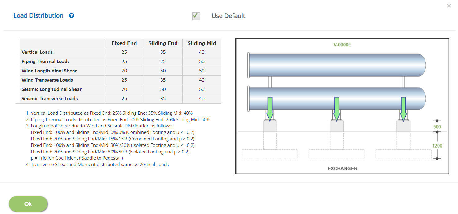
Percentage of Load on Fixed End / Sliding End / Sliding Mid
Enter the percentage of vertical load to be distributed on the fixed end.
↔ Range: 0 to 100 %
- Note: The user is not limited to give only 100% of total vertical load on both fixed and sliding ends. The user may select more than 100% or less than 100% in order to design individual supports as per user choice.
Percentage of Bundle Weight as Pull Force
Enter the percentage of bundle weight as pull force. In addition, a drop-down facility is available to select the direction (Fixed End to Sliding End or Sliding End to Fixed End) of the Bundle Pull Force to be applied on the exchanger foundation design. This bundle pull force is not applicable to Horizontal Vessel Foundation design. The bundle pull force is distributed to fixed end based on the friction developed to resist at the sliding ends. In case, the user wants to design the fixed end pedestal/footing for total bundle pull force, the sliding friction coefficient may be taken as “zero”. However, the user shall note that other longitudinal forces (wind/seismic) are also distributed/transferred according to the friction coefficient as defined. The portion of the bundle pull force for the design of sliding end pedestal/footing is the minimum of friction force developed or half of the bundle pull load applied.
The bundle pull load is applied at the center of the exchanger in the longitudinal direction and is transferred to the support as a shear and push/pull forces. If the bundle pull direction is from Fixed End to Sliding End (as a default applicable case), the push force is applied on the sliding end support and the pull force is applied on the fixed end support. In case user prefers to change the direction from Sliding End to Fixed End for any reasons (ECHORVES is not limiting the user to exercise any option), the pull force is applied on the sliding end support and the push force is applied on the fixed end support.
In case of stacked exchanger, the bundle pull force is considered at the centre line of the topmost exchanger longitudinal axis direction.
↔ Range: 0 to 200 %
As per clause 4.1.8.1 of PIP STC01015-2017, 100% of the bundle weight shall be considered as a Bundle Pull. Need not be less than 9.0kN (2,000lb) and need not be greater than total weight of the exchanger. The bundle pull design load need not be greater than the total weight of the exchanger.
- Note: If the bundles are extracted using a bundle extractor directly attached the exchanger, the bundle pull force is not transferred to pedestal/footing. In such cases, the percentage is to be entered as “zero”.
Percentage of Piping Thermal Load in Fixed End
Enter the percentage of piping thermal load in the fixed end to be considered. In this case, the remaining percentage of piping thermal is considered in the sliding end support.
↔ Range: 0 to 100 %
Load Combinations
This page allows the user to select load combinations as per applicable country code.
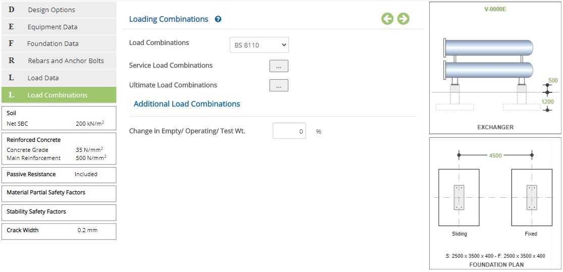 Load Combinations
Select the country code by which load combinations have to be considered. Select user-defined, to enter combinations manually, as per preference of the user.
The following are the list of country codes available for auto combinations:
- BS 8110
- EN 1992
- ASCE 2005
- ASCE 2010
- ASCE 2016
- Additional Load Combinations
Enter the percentage of change in empty / operating and test weights to add additional load combinations. The default value of “zero” will ensure that no more additional combinations are added for checking. In case of non-zero values, additional load combinations are added as like original load combinations to design the foundation based on increased load weights.
↔ Range: 0 to 100 %
As per clause 4.2.1.2 of PIP STE03360-2007, 20% increase of empty/operating weights for exchangers diameter less than 24" inches and 10% increase for exchangers diameter greater than or equal to 24 inches. 10% increase of empty/operating/test weights for horizontal vessels.
- Note: Based on the change in empty / operational / additional / test weight, SLS and ULS combinations will be created for the calculation in the back end of the program automatically. This unique facility helps to detect the critical load combination automatically by the ECHORVES for the present loads as well as increased loads.
Service Load Combinations
Click this button to open the pop-up dialog to define the service load combinations. This is a spreadsheet type input dialog - right click on the spreadsheet to add or delete rows. Alternatively, the user can copy and paste data from an external source such as Microsoft Excel.
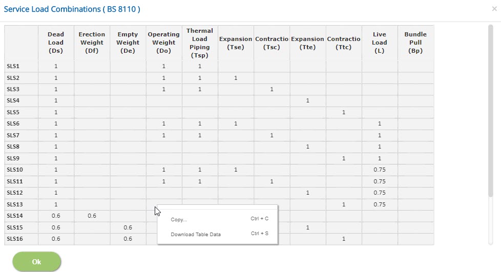
Displays the service load combinations as per the country code selected.
In case of different service load combination is required, the user-defined option is to be selected to create new service load combination as required by the user.
↔ Range: -10 to 10
- Note: For Dead Load case type, which is the first column, the factor should be a positive non-zero value.
Ultimate Load Combinations
Click this button to open the pop-up dialog to define the ultimate load combinations. This is a spreadsheet type input dialog - right click on the spreadsheet to add or delete rows. Alternatively, the user can copy and paste data from an external source such as Microsoft Excel.
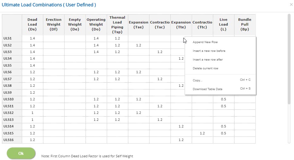
Displays the ultimate load combinations as per the code selected.
In case of different ultimate load combination is required, the user-defined option is to be selected to create new ultimate load combination as required by the user.
↔ Range: -20 to 20
- Note: For Dead Load case type, which is the first column, the factor should be a positive non-zero value.
Design Setting
Setting for various Design Data such as Soil, Reinforced Concrete, Passive Resistance, Material Partial Safety Factors, Stability Safety Factors and Crack Width are presented in this section. This setting pop-up can be accessed by clicking the bottom panel below the left navigation menu.
Soil
Soil properties and parameters shall be referred from the geotechnical report or foundation philosophy or civil/structural design basis documents of the respective project.
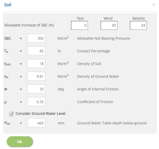 Allowable Increase of SBC (%)
↔ Range: -100 to 200 %
Allowable Net Bearing Pressure - SBC↔ Range: 25 to 1000 kN/m2
Contact Percentage - Cp↔ Range: 10 to 100 %
Density of Soil - γsoil↔ Range: 10 to 40 kN/m3
Density of Ground Water - γw↔ Range: 5 to 15 kN/m3
Angle of Internal Friction - Φ↔ Range: 0 to 60 deg
Coefficient of Friction↔ Range: 0.05 to 1.5
Ground Water Table depth below ground - μ↔ Range: 0 to 10000 mm
Pile
Pile properties and parameters such are dimension, spacing, working load, density are provided in this section.
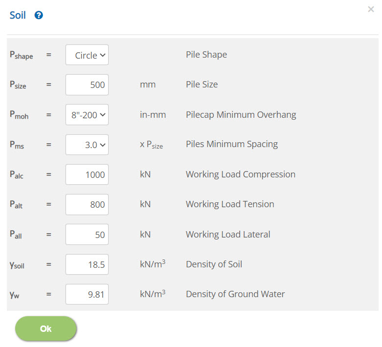 Pile Size - Psize
↔ Range: 100 to 3000 mm (4 to 120 inch)
Working Load Compression / Tension / Lateral - Palc / Palt / Pall↔ Range: 10 to 100000 kN (2 to 22500 kips)
Density of Soil - γsoil↔ Range: 10 to 40 kN/m3 (60 to 250 pcf)
Density of Ground Water - γw↔ Range: 5 to 15 kN/m3 (30 to 100 pcf)
Reinforced Concrete Properties (BS 8110)
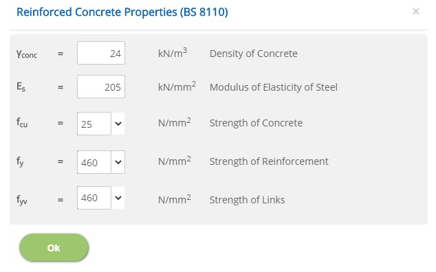 Density of Concrete - γconc
↔ Range: 10 to 40 kN/m3
Modulus of Elasticity of Steel - Es↔ Range: 50 to 300 kN/mm2
Strength of Concrete - fcu↔ Range: 15 to 100 N/mm2
Strength of Reinforcement - fy↔ Range: 150 to 2000 N/mm2
Strength of Links - fyv↔ Range: 150 to 2000 N/mm2
Reinforced Concrete Properties (BS EN 1992-1-1)
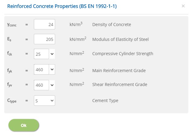 Density of Concrete - γconc
↔ Range: 10 to 40 kN/m3
Modulus of Elasticity of Steel - Es↔ Range: 50 to 300 kN/mm2
Compressive Cylinder Strength - fck↔ Range: 15 to 100 N/mm2
Main / Shear Reinforcement Grade - fyk / fyv↔ Range: 150 to 2000 N/mm2
Cement Type - CtypeSelect the cement type.
Reinforced Concrete Properties (ACI 318M)
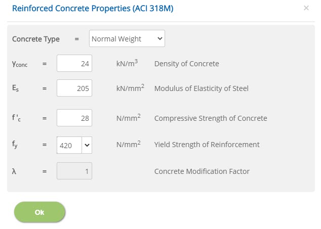 Density of Concrete - γconc
↔ Range: 10 to 40 kN/m3 (60 to 250 pcf)
Modulus of Elasticity of Steel - Es↔ Range: 50 to 300 kN/mm2 (7000 to 45000 ksi)
Compressive Strength of Concrete - f'c↔ Range: 15 to 100 N/mm2 (1 to 15 ksi)
Yield Strength of Reinforcement - fy↔ Range: 150 to 2000 N/mm2 (20 to 300 ksi)
Concrete Modification Factor - λ↔ Range: 0.75 to 1
Passive Resistance
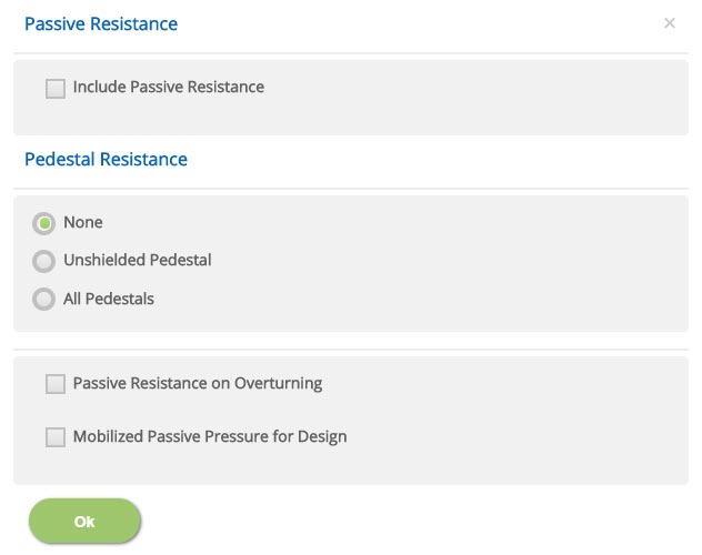
Passive Resistance
☐ Include Passive Resistance: Select if passive resistance is to be considered. Other options in the following have no effect if this is not selected.
Pedestal Resistance
☉ None: Select this option if passive resistance is not to be considered on pedestals.
☉ Unshielded Pedestals: Select this option if passive resistance is to be considered on pedestals which are fully or partially exposed to soil passive pressure without being shielded by others pedestals ahead in the direction of the shear force.
☉ All Pedestals: Select this option if passive Resistance is to be considered on pedestals irrespective of the shielding condition from other pedestals. User can select this option if it is presumed that all pedestals are fully effective in offering the passive resistance.
Other
☐ Passive Resistance on Overturning: Select this option if passive resistance is to be considered in resisting overturning. (By default, only sliding is considered).
☐ Mobilized Passive Pressure for Design: Select this option if pedestals are to be designed for mobilized passive forces (Passive force generated due to applied shear forces).
Material Partial Safety Factors
Enter the material safety factors on selection of British or European Standard and Design Unit from Design Option.
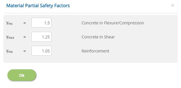
Flexure/Compression / Concrete in Shear / Reinforcement
γmc, γmcs, γms
↔ Range: 1 to 2
Stability Safety Factors
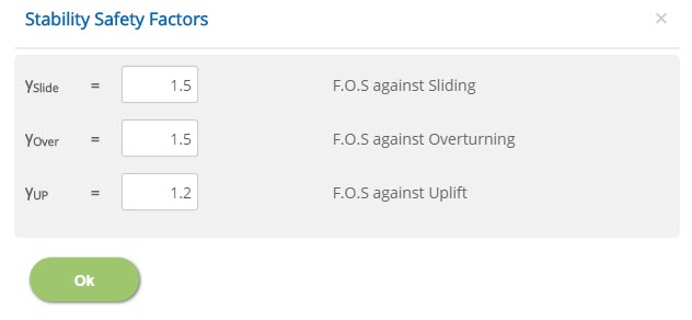 F.O.S against Sliding / Overturning / Uplift
 γslide, γover, γUP
↔ Range: 1 to 5
Crack Width
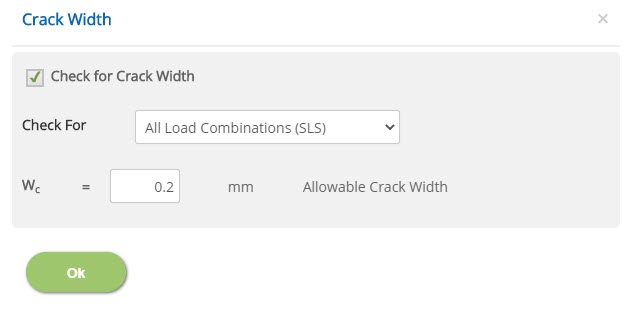
☐ Check for Crack Width: Check this option to consider crack width.
Check For☐ All Load Combinations (SLS): Select this option to check crack width for all load combinations.
☐ Sustained Load Combinations (SLS): Select this option to check crack width for sustained load combinations.
↔ Range: 0.05 to 0.6
National Annex
Select the National Annex after selecting the European Standard in Design Option.
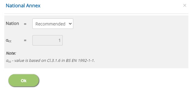
Nation
Select the National Annex option for the relevant factors to be considered in the design.
αcc
Enter the value for the User Defined National Annex option. For other options, this is not editable.
↔ Range: 0.7 to 1.2
Error Handling
Errors and Warnings are generated to prevent any inadvertent error in the input data. This section describes how to handle the errors and warnings. These errors are displayed at the bottom of the input page when the data in one or more input fields invalidate each other.
- Note: What is the meaning of a Range used in the user manual? Range is a predefined limit set in the application to ensure user to enter values within these limits by providing a warning to the user. This will avoid user to enter any illogical values by mistake which may crash the program or abrupt end of the calculation. In case user wants to change these limits, the same may be communicated to EC PLUS Technical Support Team using Contact Us.
| # | Error | Reason | Solution |
|---|---|---|---|
| 1 | Warning : Centerline of vessel center from top of pedestal is too short | Distance from top of pedestal to centre of vessel is too short. | Check / increase the distance between centerline of equipment and top of pedestal (Hcl) or check / decrease the height of pedestal from FGL / HPP (Hag) or check / correct the diameter of Equipment (D1). |
| 2 | Warning : Insufficient spacing between exchanger upper and lower tubes | Distance between lower and upper tubes of exchanger is insufficient. | Check / decrease distance between centerline of equipment and top of pedestal (Hcl) or check / increase spacing between two exchangers (Se) or check / correct diameters of equipment (D1) and (D2). |
| 3 | Warning : Vessel length is too short for the given saddle spacing | Length of the vessel is too short while compared with the provided saddle spacing. | Check / correct equipment length (L) with respect to spacing between saddles (Sc) or check / correct spacing between saddles (Sc) with respect to equipment length (L). |
| 4 | Warning : Reduction of Soil cover exceeds Foundation Depth | Reduction of soil cover is greater than the depth of the foundation. | Provide reduction in soil cover (Scr) with respect to foundation depth (Df) or check / correct foundation depth (Df) with respect to reduction in soil cover (Scr). |
| 5 | Warning : Reduction of Soil cover exceeds Fixed End Foundation Depth | Reduction of soil cover is greater than the fixed end foundation depth. | Provide reduction in soil cover (Scr) with respect to foundation depth (Df) or check / correct foundation depth (Df) with respect to reduction in soil cover (Scr). |
| 6 | Warning : Effective diameter shall not be greater than 1.5 times equipment diameter | Effective diameter is greater than 1.5 times the diameter of the equipment. | Check / increase the diameter of the equipment or check / decrease the effective diameter. |
| 7 | Warning : Effective height shall not be greater than 1.5 times equipment height | Effective height is greater than 1.5 times the height of the equipment. | Check / increase the height of the equipment or check / decrease the effective height. |
| 8 | Warning : Effective length shall not be greater than 1.5 times equipment length | Effective length is greater than 1.5 times the length of the equipment. | Check / increase the length of the equipment or check / decrease the effective length. |
| 9 | Warning : Minimum edge distance (Z Direction) required is "MinSpacing" * bolt dia | Edge distance is lesser than the minimum spacing * bolt diameter in Z direction. | Check / correct the edge distance in Z direction. |
| 10 | Warning : Minimum edge distance (X Direction) required is "MinSpacing" * bolt dia | Edge distance is lesser than the minimum spacing * bolt diameter in X direction. | Check / correct the edge distance in X direction. |
| 11 | Error: Insufficient pedestal width for the cover and reinforcement sizes | Width of the pedestal provided is insufficient to accommodate provided cover and reinforcement sizes. | Check / correct size of pedestal or clear cover or reinforcement diameter. |
| 12 | Error: Fixed End: Insufficient pedestal width for the cover and reinforcement sizes | Width of the pedestal provided is insufficient to accommodate provided cover and reinforcement sizes at fixed end. | Check / correct size of pedestal or clear cover or reinforcement diameter. |
| 13 | Error: Sliding End: Insufficient pedestal width for the cover and reinforcement sizes | Width of the pedestal provided is insufficient to accommodate provided cover and reinforcement sizes at sliding end. | Check / correct size of pedestal or clear cover or reinforcement diameter. |
| 14 | Error: Pedestals are too close and clashing | One or more pedestals provided are very close and clashing with each other. | Revise spacing between saddles or size of pedestals. |
| 15 | Error: Insufficient footing thickness for the cover and reinforcement sizes | Footing thickness provided is insufficient to accommodate the provided cover and reinforcement. | Revise footing thickness or clear cover or reinforcement diameter. |
| 16 | Error: Fixed End: Insufficient footing thickness for the cover and reinforcement sizes | Footing thickness provided is insufficient to accommodate the provided cover and reinforcement at fixed end. | Check / correct size of pedestal or clear cover or reinforcement diameter. |
| 17 | Error: Sliding End Insufficient footing thickness for the cover and reinforcement sizes | Footing thickness provided is insufficient to accommodate the provided cover and reinforcement at sliding end. | Check / correct size of pedestal or clear cover or reinforcement diameter. |
| 18 | Error: Effective diameter cannot be less than equipment diameter | Effective diameter is lesser than the diameter of the equipment. | Check / correct the effective diameter or diameter of the equipment. |
| 19 | Error: Effective height Cannot be Less than equipment height | Effective height is lesser than the height of the equipment. | Check / correct the effective height or height of the equipment. |
| 20 | Error: Effective length cannot be less than equipment length | Effective length is lesser than the length of the equipment. | Check / correct the effective length or length of the equipment. |
| 21 | Error: Bolts position in Z direction should be inside the pedestal size | Position of bolts in Z direction is outside the pedestal. | Check / correct the position of bolt to locate it within the pedestal in Z direction. |
| 22 | Error: Bolts position in X direction should be inside the pedestal size | Position of bolts in X direction is outside the pedestal. | Check / correct the position of bolt to locate it within the pedestal in X direction. |
| 23 | Error: Pedestal overstepping | Pedestal provided is overstepping with the base block. | Check / correct size of footing or pedestal or location information. |
| 24 | Error: Pedestal overstepping at Fixed End | Pedestal provided is overstepping with the base block at the fixed end. | Check or correct size of footing or pedestal or location information. |
| 25 | Error: Pedestal overstepping at Sliding End | Pedestal provided is overstepping with the base block at the sliding end. | Check or correct size of footing or pedestal or location information. |
| 26 | Error: Fixed and Sliding End Foundations clash | Foundation is clashing with the fixed and sliding end. | Check or correct size of fixed end footing or sliding end footing or spacing between Saddles. In such case, it is recommended to proceed with a combined foundation instead Isolated foundation for each support. |
| 27 | Error: Equipment Saddle Base Inside the Footing | In case of combined footing, location of equipment saddle base is inside the footing. | Check / correct FGL to Saddle Base (Height above Ground) or Foundation Depth or Footing Thickness, in combined footing. |
| 28 | Error: Equipment Saddle Base Inside the Fixed End Footing | In case of isolated footing, location of equipment saddle base is inside the fixed end footing. | Check / correct FGL to Saddle Base (Height above Ground) or Foundation Depth or Footing Thickness, in isolated pad (fixed end). |
| 29 | Error: Equipment Saddle Base Inside the Sliding End Footing | In case of isolated footing, location of equipment saddle base is inside the sliding end footing. | Check / correct FGL to Saddle Base (Height above Ground) or Foundation Depth or Footing Thickness, in isolated pad (sliding end). |
| 30 | Error: Footing Thickness out of range | Thickness of the footing provided is out of the range. | Check / correct depth of foundation (Df) or request to change this limit to EC PLUS Technical Support Team using Contact Us. |
| 31 | Error: Footing Plan Dimension(s) out of range | One or more of footing plan dimension is out of the range. | Check / correct foundation plan dimensions input or request to change this limit to EC PLUS Technical Support Team using Contact Us. |
| 32 | Error: Fixed End Foundation Depth out of range | Depth of foundation at fixed end is out of the range. | Check / correct depth of foundation at fixed end or request to change this limit to EC PLUS Technical Support Team using Contact Us. |
| 33 | Error: Fixed End Footing Thickness out of range | Thickness of footing at fixed end is out of the range. | Check / correct fixed end footing thickness or request to change this limit to EC PLUS Technical Support Team using Contact Us. |
| 34 | Error: Fixed End Footing Plan Dimension(s) out of range | One or more of footing plan dimension at fixed end is out of the range. | Check / correct fixed end foundation plan dimensions input or request to change this limit to EC PLUS Technical Support Team using Contact Us. |
| 35 | Error: Sliding End Foundation Depth out of range | Depth of foundation at sliding end is out of the range. | Check / correct sliding end foundation plan dimensions input or request to change this limit to EC PLUS Technical Support Team using Contact Us. |
| 36 | Error: Sliding End Footing Thickness out of range | Thickness of footing at sliding end is out of the range. | Check / correct sliding end footing thickness or request to change this limit to EC PLUS Technical Support Team using Contact Us. |
| 37 | Error: Sliding End Footing Plan Dimension(s) out of range | One or more of footing plan dimension at sliding end is out of the range. | Check / correct sliding end foundation plan dimensions input or request to change this limit to EC PLUS Technical Support Team using Contact Us. |