Contents
ECMAT - Technical Reference Manual
Last Updated: September 06, 2020
Version: 1.0
1.0 Introduction
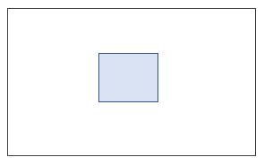
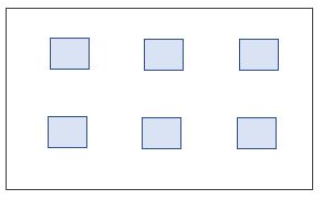
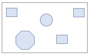
This technical reference presents the theory and general practice for the design of mat foundations using ECMAT. A mat, generally a large and thick concrete pad, comprises single or multiple pedestals (piers) arranged in 'n x n' grid pattern or irregular fashion as required. The common shape of a mat foundation is rectangular and non-rectangular shapes are occasionally adopted.
|
|
|
| Isolated Type | Regular Grid Type | Irregular Grid Type |
The design of a mat foundation, like any other foundation, is to carry the superstructure loads safely to the ground without exceeding the soil bearing capacity or the pile capacity. The design should ensure adequate stability against destabilizing actions such as sliding and overturning forces. The strength design of the pad and pedestal for reinforcement is usually part of the foundation design process.
The design of a mat foundation with a concentric single pedestal, referred as isolated foundation, and with a single load case of vertical load is a simple calculation method. But the calculation procedure becomes complex and laborious with multiple pedestals and more load combinations. Spreadsheet solutions are sometimes employed but they have inherent limitations. A versatile computer program such as ECMAT is advised which facilitates the modeling and design of mat foundations of complex type.
The design methods for a mat foundation are presented in the following sections.
2.0 Service Loads Design
Service loads are the normal loads under which the foundation serves its purpose with acceptable conditions such as settlement, stability, and durability.
2.1 Soil Bearing Pressure
The calculation of soil bearing pressure that develops at the base of the pad due to applied loads is presented as follows.
2.1.1 Pressure Distribution
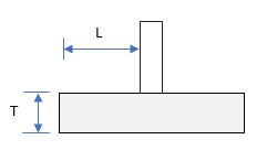
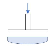
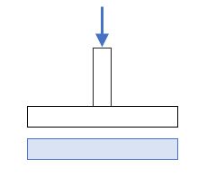
For the foundations supported on soil, ECMAT uses linear soil pressure distribution. The actual distribution is nonlinear, however, for all practical design purposes, it is acceptable to use linear distribution when the pad is sufficiently rigid. As a rule of thumb, a ratio of outstand length to thickness below five (5) ensures adequate rigidity.
|
L / T <= 5 (Rigid)
L / T > 5 (Flexible) |
|
|
|
Nonlinear Distribution
Flexible |
Linear Distribution
Rigid |
2.1.2 Foundation Loads
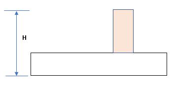
The total load on the foundation base is computed as below:
| Total Vertical Load | P | ∑ Fy + ∑ Pedestal Self Weight + Pad Self Weight + Soil Overburden |
| Total Moment about X | Mx | ∑ mx + ∑ (Fz * H) |
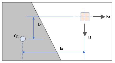
| Total Moment about Y | My | ∑ my + ∑ (Fx * lz) + ∑ (Fz * lx) |
| Total Moment about Z | Mz | ∑ mz + ∑ (Fx * H) |
| Total Shear X | Sx | ∑ Fx |
| Total Shear Z | Sz | ∑ Fz |
|
|
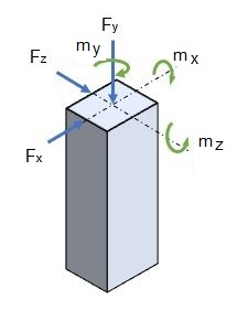
| Fx | Force in X direction on pedestal | |
| Fy | Force in Y direction on pedestal | |
| Fz | Force in Z direction on pedestal | |
| mx | Moment about X on pedestal | |
| my | Moment about Y on pedestal | |
| mz | Moment about Z on pedestal | |
| H | Height of pedestal from the base of the foundation | |
| lx | Distance between cg of base pressure to the pedestal with force Fz in X direction | |
| lz | Distance of cg of base pressure to the pedestal with force Fx in Z direction | |
| A | Area of the base | |
| Zxx | Section modulus of base about X-X | |
| Zzz | Section modulus of base about Z-Z |
For soil overburden on top of pad, ECMAT considers two cases:
- ❶ Full Soil Cover
- ❷ Minimum Soil Cover
When the water table is present within the foundation depth, buoyancy effect is considered as below:
Uplift load = (Water table Height * Density of Water) * Base Area
This uplift load is deducted from the total vertical load. Since the water table is subject to seasonal variation,
ECMAT considers the case without water table as well. The water table effect is checked with only minimum soil cover condition.
2.1.3 Bearing Pressure
The base pressure at four corners is then calculated as
pi
= P / A ± (Mx + P * ez) / Zzz ± (Mz + P * ex) / Zxx
Where
ex
and
ez
are eccentricities of total vertical load in X and Z directions.
The above formula is applicable for only small moments, i.e., when the base is in full contact with the soil.
For larger moments, corners are likely to be lifted. For such cases,
the maximum pressure, pmax is determined by an iteration method. It shall be noted that foundation shall be
stable against overturning to determine the bearing pressure.
For a safe foundation design, the calculated bearing pressure should be less than the gross bearing capacity.
Gross bearing capacity = Allowable Net Bearing Capacity (SBC) * Soil overburden height * Soil Density
2.1.4 Contact Ratio
The soil bearing contact ratio is defined as:
Contact ratio = Bearing Area / Base Area
When the corners are out of contact with soil, the contact ratio is less than 1. The contact is also expressed in percentage (%).
The foundation is stable when the contact is greater than 0%. However, to avoid over-stressing of soil, it is recommended that at least 70%
soil contact is achieved.
2.2 Foundation Stability
2.2.1 Sliding
Sliding is the phenomenon by which the foundation tends to move laterally due to shear forces.
Stability of the foundation against sliding is offered by the total vertical loads and the friction
between the concrete base and soil. Sliding is more critical when minimum soil cover condition
and buoyancy effect due to water table are present.
Factor of safety against sliding:
FOS = P * μ / Fv
| Where | μ | Friction Factor | |
| Fv | Resultant Shear Force = [ Fx2 + Fz2 ]1/2 |
When passive pressure option is enabled, the passive pressure components on pedestal and pad will be included in the
sliding resistance.
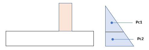 Factor of safety against sliding:
FOS = ( P * μ + Pc1 + Pc2) / Fv
Factor of safety against sliding:
FOS = ( P * μ + Pc1 + Pc2) / Fv
Pc1 Passive force on Pedestal
Pc2 Passive force on Pad
The passive forces on pad and pedestal is calculated along the direction of resultant shear force. When the soil compaction around the pedestal is
doubtful, passive pressure resistance from pedestals shall be ignored.
The passive pressure at base = γsoil * Kp * h [γsoil - Soil Density; Kp - Passive Pressure Coefficient; h - height of soil above]
The factor of safety against sliding is specified in the range of 1.5 to 2.5 depending on the importance of the structure and the probability of the loads being exceeded.
2.2.2 Overturning
Overturning tends to occur when the foundation is subject to direct moment and moment due to shear force.
Stability of the foundation against overturning is provided by virtue of self weight, applied vertical loads and pad dimensions.
Overturning is more critical when minimum soil cover condition and buoyancy effect due to water table are present.
Factor of safety against overturning in each axis (X and Z):
FOS = Resisting Moment / Overturning Moment
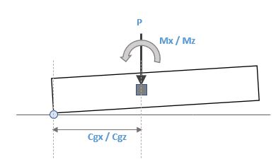
| Resisting Moment about X / Z = P * Cgz and P * Cgx |
| Overturning Moment about X / Z = Mx and Mz |
| Cgx / Cgz - The cg distance about X / Z. |
When passive pressure option is selected, the passive pressure components on pedestal and pad will be included in the overturning resistance.
The factor of safety against overturning is specified in the range of 1.5 to 2.5 depending on the importance of the structure and the probability of the loads being exceeded.
2.2.3 Uplift
Uplift of the foundation is likely to occur when the foundation is subject to high tension forces.
Stability of the foundation against any tensile load is provided by the self weight of the foundation.
Minimum soil weight and buoyancy effect should be considered to arrive at the counterweight of the foundation against uplift.
Factor of safety against uplift:
FOS = Self weight / Tension Load
The factor of safety against uplift is specified in the range of 1.2 to 2.0 depending on the importance of the structure and the probability of the loads being exceeded.
2.2.4 Torsional Resistance
It is a stability against twisting of pad due to torsion and shear forces on pedestals. This can be checked using ECMAT as an option. The computation of torsional resistance involves discretization of soil pressure area into small elements and summing up individual frictional resistances against the torsion.
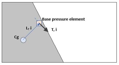
Torsional Resistance:
TR = Σ LTi * Tri
LTi Lever arm between the Cg and the discrete base pressure
Tri Torsional resistance from the discrete base pressure
= Average pressure of discrete * Area of discrete * μ
The torsional effect is synonymous with sliding - the same factor of safety for sliding is applied.
2.2.5 Torsion reduced sliding resistance
When torsion and shear forces are coexisting, the sliding resistance is reduced by the torsion.
The frictional resistances from the discrete elements are first to
resist the torsion and the remaining resistances from discrete elements resist the shear.
The reduction in shear resistance due to the presence of torsion is negligible unless the foundation is subject to large torsional moment.
2.2.6 Crack Width
Crack width on the pad top and bottom surface due to moment is sometimes set a limit to ensure durability.
The width of the crack also depends on section size and reinforcement.
The calculation, however, is different for various national design standards.
3.0 Ultimate Loads Design
The pad and pedestals section sizes and their reinforcement design is carried out in the strength design.
3.1 Pad
Strength design process for pad section involves determination of bending moment, one-way (wide beam) shear
and two-way (punching) shear at critical locations as defined
by the respective national design standards. The design forces are then checked against the capacity of the section.
3.1.1 Bending Moment
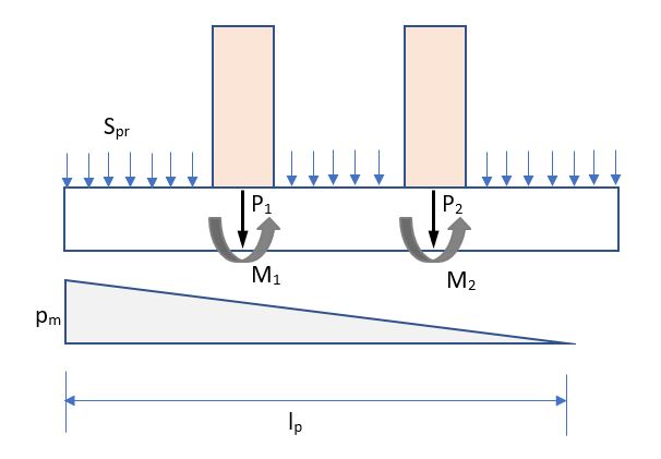
One way bending moment in each direction is determined and used to calculate the required reinforcement in the respective direction and face(Top and Bottom). Bearing pressure distribution, self weight of pad, soil weight above and pedestal loads are required to calculate the bending moment.
|
|
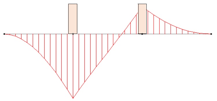
| Loads | Bending Moment Diagram |
Bending Moment at any location (x) = x2/6 * (2 *pm + px) - Spr * x 2/2 - Sw * x 2/2 - ∑[Pn * (x-dn) + Mn]
| pm | Maximum Edge Bearing Pressure |
| px | Bearing Pressure at x location |
| Spr | Soil Overburden Pressure |
| Sw | Self Weight |
| Pn | Pedestal Vertical Load (nth) |
| dn | Distance of pedestal center from edge (nth) |
| Mn | Pedestal Moment (nth) |
3.1.2 One way Shear
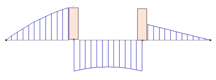
One way shear force is calculated using the load distribution given above.
|
| Shear Force Diagram |
One way Shear at any location (x) = x * (pm + px)/2 - Spr * x - Sw * x - ∑[Pn]
3.1.3 Punching Shear
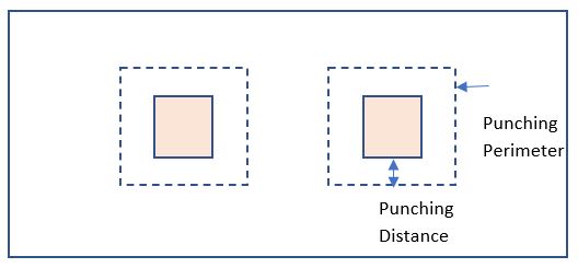
Punching shear is calculated for each pedestal location. The punching distance from pedestal edge varies for different national standards.
|
| Punching Stress Diagram |
Punching Shear Stress = Punching perimeter * depth / Punching Load
It shall be noted that the punching perimeter reduces when the pedestal is near the corner.
3.2 Pedestal
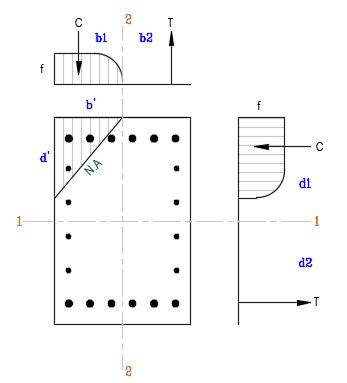
For pedestal (pier) design, unless the design is from other structural analysis and design software, the design forces such as axial load, biaxial bending moments and biaxial shear forces are required and they are calculated at the top of the pad (base of pedestal). ECMAT uses biaxial interaction curve to optimize and provide safe design for the reinforcement design for pedestals.
|
b' and d' are the distances that define the neutral axis C and T compression and tension in the stress blocks Moment capacities about 1-1 and 2-2 for the applied axial load M1-1 = C * d1 + T * d2 M2-2 = C * b1 + T * b2 Section adequate biaxial moment capacity is established as m1-1 / M1-1 ≤ 1 and m2-2 / M2-2 ≤ 1 Where m1-1 and m2-2 are the applied moments Note: The stress distribution profile is rectangular parabolic for British and European Standards and rectangular for American Standard. |
| Biaxial Stress Diagram |
4.0 References
| ACI 318 | Building Code Requirements for Structural Concrete | |
| ACI 224R-01 | Control of Cracking of Concrete Structures | |
| BS 8110-1 | Structural use of Concrete. Code of Practice | |
| BS EN 1992-1-1 | Design of concrete structures. General rules and rules for buildings |