> >
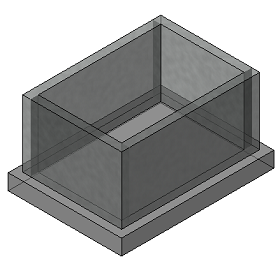
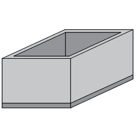
RC Rectangular Pit Design
|
|
Download Sample Report |
The scope of this calculation module is to design concrete pit elements subjected to backfill pressure from outside, content pressure from inside, surcharge and live loads. The moment and shear capacity of each element is computed. Additionally, crack width check is also carried out to satisfy liquid retaining structure requirements.
Standards: British, European and American (SI and Imperial Units)
Features
- The module gives the user ample amount of choices so as to allow them to mould the structure similar to that of actual site conditions such as,
- Top slab support condition
- Monolithic
- Non monolithic
- Steel Platform
- Not present
- Content present
- Liquid
- Sand
- Nil / Empty
- Load combinations - Includes pit empty condition, operating case, water testing case, for different defined load combinations (SLS and ULS).
- Reinforcement options
- An option is provided for each pit element for single layer (tension only) reinforcement, by default double layer (both compression and tension) reinforcement is considered.
- For wall reinforcement an option is provided for providing same reinforcement for both short as well as long wall elements.
- Stability checks for uplift and bearing pressure is carried out for the predefined load combinations.
- Concrete pit is designed by considering following three cases,
- No content inside pit, with backfill present (as per ground level position).
- Operating case - content present inside and backfill present outside (as per ground level position).
- Test case - water present inside pit for full height with no backfill outside.
- The module also computes the moment and shear capacity of each pit element to resist the moment and shear stress induced due to various loading conditions as defined.
- In addition, the calculation checks the design surface crack width of the concrete pit as an option.
Design Considerations
- Ground level and wall elevation level determines whether pit is located completely or partially under the ground.
- Ground level and ground water level determines the level of submerged soil present outside the pit.
- For bottom slab design the effect of moment transferred from both wall and slab projection (if present) is taken into consideration.
- The effect of bearing pressure is also taken into consideration for bottom slab as well as slab projection design to calculate the net moment induced.
- Moment and shear coefficients values for wall elements were calculated as per Roark’s formula for stress and strain.
- Moment and shear coefficients values for slab elements were calculated as per code provision taking into consideration the option for torsional provision.
- Moment is computed for both support as well span region in the respective directions (horizontal and vertical for wall, length and width for slab) for each element.
National Standards Available
British Standard
European Standard
- National Annex of several countries such as Europe (Recommended), UK, Finland, Ireland, Malaysia, Norway, Singapore, Sweden are considered.
- Additionally, an option is provided to define the coefficients directly by the user.
American Standard
- The calculation allows the user to design the section in both imperial and metric units.
References
- BS 8110-1:1997 - Structural use of concrete - Part 1: Code of practice for design and construction.
- EN 1992-1-1:2004 - Design of concrete structures - Part 1-1: General rules and rules for buildings.
- ACI 318-14 - Building Code Requirements for Structural Concrete.
- ACI-224R-01 - Control of Cracking in Concrete Structures.
- Roark’s Formulas for Stress and Strain - Seventh Edition by Warren C. Young and Richard G. Budynas.
Revision
- Ver 1.0 - Original version
|
|
Download Sample Report |