> >
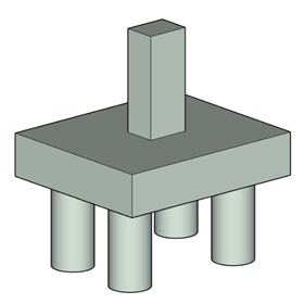
RC Pilecap Design - 4 Piles
|
|
Download Sample Report |
The scope of this calculation is to design a pile cap for the given factored axial load which is distributed proportionately to a 4 - pile system using strut and tie analogy and to compute the pile reaction forces from the unfactored axial load which may be used for pile design. A compression check is carried out to assess the design capacity of the pile cap.
Strut and Tie Analogy
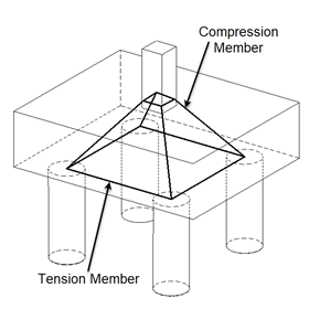
The factored axial load is divided among the piles based on the column eccentricity and resolved into compression and tension forces using truss analogy as follows,
Force on each pile, F = Fult * ((s / 2 ± ex) * (s / 2 ± ey)) / s
The angles are computed as follows,
Vertical angle, θ = tan-1 (d / (√((s / 2 ± ex)2 + (s / 2 ± ey)2)
Horizontal angle, α = tan-1 [{s / 2 ± ex} / (s / 2 ± ey)]
Using the above computed angles the forces are resolved into,
Compressive force, C = F / sin(θ)
Tensile force, T = C * cos(θ) * cos(α)
Critical Shear Section
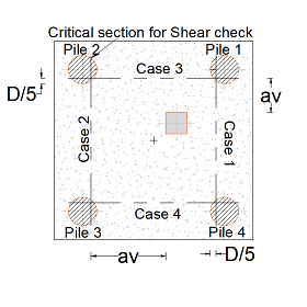
Critical sections of shear are assumed to be located at 20% of the pile inside the face of the pile.
The distance from the critical section of shear in pile (D/5) to column face is assumed as the critical section distance for a pile, which is used in the computation of enhanced shear strength for the respective pile.
Based on column eccentricity the enhanced shear strength will vary for each pile and hence they are calculated individually.
Features
- The design calculation accommodates the basic assumptions of truss analogy (strut and tie method).
- The check for minimum depth of pile cap is done based on the spacing of piles.
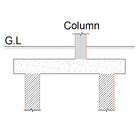
- The design calculation is carried out for pile cap under the influence of axial load in normal or eccentric conditions, from column.
- The module allows the user to choose the type of column geometry best suited for their design such as:
- Rectangular column
- Circular column
- Similarly, another option is provided to choose the pile geometry as follows:
- Circular piles
- Square piles
Design Considerations
- The piles are considered to be hinged to the pile cap hence no bending moment is transmitted.
- The spacing between piles should not be less than the pile diameter, a general warning is provided in case pile spacing less than 3 times the diameter - this does not hinder with the calculation however.
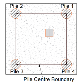
- The column eccentricity is controlled such that the column centre does not go beyond the pile centre boundary.
- In the truss analogy the force from the column is assumed to be transmitted by a triangular truss action with concrete providing the compressive members of the truss and steel reinforcement providing the tensile member.
- The pile design is carried out based on the reaction force computed from the unfactored load by considering the eccentricity along with self-weight of pile cap.
- In case of square piles for the effective width and shear plane width calculation, the pile area is converted to the equivalent pile diameter.
- Similarly, in case of circular piles, the pile area is converted to equivalent square side and from which the perimeter for shear action is taken for punching shear calculation.
- The shear failure of sections without shear reinforcements is considered to occur on a plane inclined at 30° to the horizontal.
- The module checks for allowable shear stress against the design shear stress calculated with enhanced shear capacity.
- Punching shear check is carried out at the column face and at a perimeter of 1.5 times pile cap depth.
National Standards Available
British Standard
References
- BS 8110-1:1997 - Structural use of concrete - Part 1: Code of practice for design and construction.
- “Reinforced Concrete Designer’s Handbook” - Reynold’s and Steedman.
Revision
- Ver 1.0 - Original version
|
|
Download Sample Report |