> >
Fixed Baseplate Design
|
|
Download Sample Report |
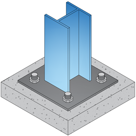
The scope of ECBASEPLATE is to design fixed base plate for biaxial moments and axial loads transferred from steel column to foundation concrete. Axial load can either be tensile or compressive in nature. The tensile force is dispersed to the foundation concrete with the help of holding down bolts and anchor plates and the compressive force is resisted by concrete bearing stress. ECBASEPLATE application follows the design principles of American standard incorporating the relevant factors for both LRFD (Factored load combinations) and ASD (Service load combinations) in design calculations accordingly.
The loading conditions in the base plate system have been considered for 4 categories based on the reaction forces:
- Pure compression - ( Compressive load with no moment ).
- Small moment - ( Compressive load with moment, e ≤ ecr ).
- Pure tension - ( Tensile load with no moment ).
- Large moment - ( Tensile or compressive load with moment, e > ecr ).
For bolt anchorage checks, the different failure modes checked are as follows:
- Tension
- Shear
Forces Acting
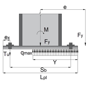
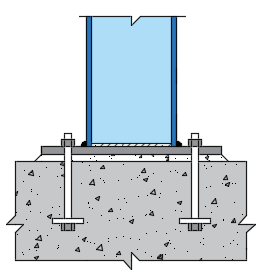
Reaction forces for large moment case – compressive force is considered to be acting at the centroid of the compression block which is assumed to be rectangular and tension forces are considered to be acting at the holding down bolts computed by using static equilibrium condition.
Fy + Tu - ( qmax * Y) = 0
M - (Fy * Lpl / 2) - Tu * (Sb + ex) + (qmax * Y * Y2 / 2) = 0
Features
- User is allowed to choose a steel section from the following categories:
- I section
- Rectangular hollow section
- Square hollow section
- Welded section (user defined)
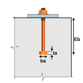
- Bolt anchorage - Bolt parameters can be input by the user for checking the anchorage failure modes based on:
- Defined.
- The application calculates the anchorage capacity based on the properties defined where, bolt parameters can either be edited by the user or the program selects the standard dimensions based on bolt dia.
- Not Defined.
- The application allows the user to directly input the anchorage capacity of bolts.
- The user can select standard bolt grades or input the yield and ultimate strength for bolts as per their requirements.
- An option is provided to choose the major axis (X or Z) for the section.
- User can either choose to include or ignore the reinforcement effect for anchorage checks.
- Optional weld check provided to include the design of weld capacity.
- Loads and Load Combinations can be easily imported from Microsoft Excel through clipboard or STAAD input file.
- The critical governing case is displayed by the program from the different load combinations given to aid the user in selecting the best configuration and ensure failure does not occur.
Design Considerations
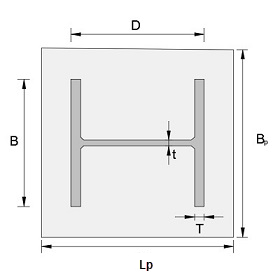
- The column is assumed to be concentric to the base plate
- All welds are fillet welds and the weld strength relate to the minimum strength of the connected parts and the class of electrode used.
- The bolts are doubly symmetrical and are spaced along the width of the base plate.
- The bolts cannot lie beyond the line drawn at 45° outwards from the edge of the column flange.
- The calculation involves determining the bearing length for the applied load combination using static equilibrium conditions.
- The base plate is checked for compression and bearing capacity of the connection along with the plate thickness.
-
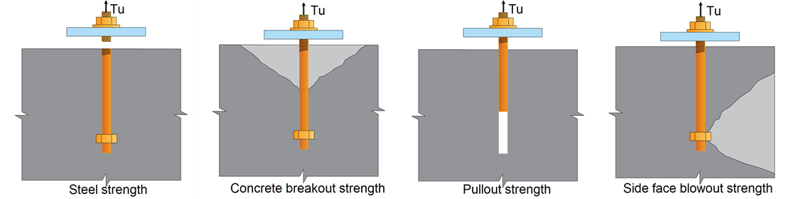
Bolt anchorage checks are carried out for tension involve the following failure modes:
1. Steel strength.
2. Concrete breakout strength.
3. Anchorage reinforcement strength (When reinforcement effect is considered).
4. Pullout strength.
5. Side face blowout strength.
-
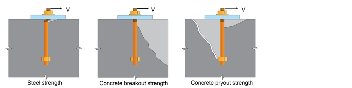
Bolt anchorage checks are carried out for shear involve the following failure modes:
1. Steel strength.
2. Concrete breakout strength.
3. Anchorage reinforcement strength (When reinforcement effect is considered).
4. Pryout strength.
- Tension and Shear Interaction ratio is computed taking into account the net tension and shear capacity (minimum capacity of all anchorage checks) of the system.
- When the option is selected to weld the washer plates to baseplate, the program considers all bolts to resist the shear force. If not selected, only the bolts on front are considered effective to resist applied shear.
- When grout pads are provided, the shear strength of the anchor bolt is reduced, due to the effect of anchor bolt bending that might arise from cracking of grout.
National Standards Available
American Standards
- The calculation allows the user to design in both imperial and metric units.
References
- AISC 360-16 “Specification for Structural Steel Building”.
- ACI 318-19 “Building Code Requirements for Structural Concrete”.
- Steel Design Guide 1 “Base Plate and Anchor Rod Design”.
Revision
- Ver 1.0 - Original version
|
|
Download Sample Report |