Help Topics
ECCOLUMN - Reinforced Concrete Column Design
This part of user manual describes how to use ECCOLUMN for the design of Reinforced Concrete Column. ECPlus applications are designed as wizard type which is a step by step guided input procedure. If you are new to ECPlus applications, click here for general guidance.
Prerequisites: The user is expected to have a basic understanding of foundation design concepts.
The minimum input data required to use this application is as follows:
- ❶ Slenderness Conditions
- ❷ Loads and Moments at Top and Bottom
- ❸ Allowable safety factors
- ❹ Material Properties
Dimensions
This page allows to select the dimensions of the concrete column.
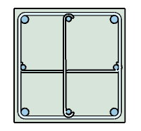
Rectangular Column
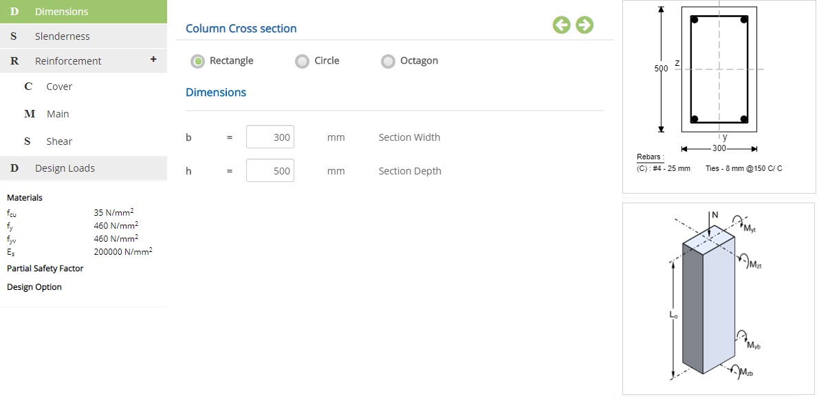 Column Cross section
☉Rectangle: Select this option to design a rectangular column.
☉Circle: Select this option to design a circular column.
☉Octagon: Select this option to design a octagon column.
Enter the width of the rectangular concrete column.
↔ Range: 120 to 2000 mm
Enter the depth of the rectangular concrete column.
↔ Range: 120 to 2000 mm
Circular Column
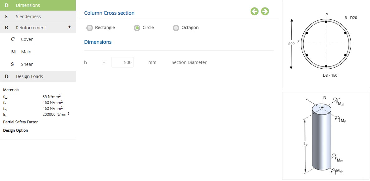 Section Diameter - h
Enter the diameter of the circular concrete column.
↔ Range: 120 to 2000 mm
Octagonal Column
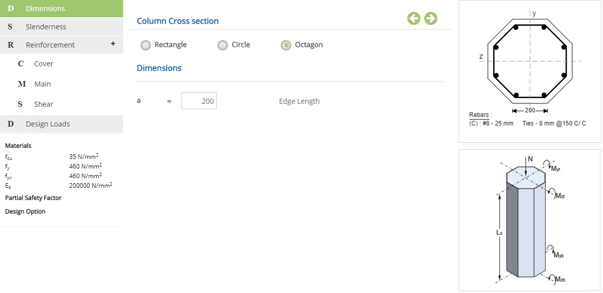 Edge Length - a
Enter the edge length of the octagon.
↔ Range: 120 to 2000 mm
Slenderness
This page allows to select the slenderness properties of the column section.
Short Column
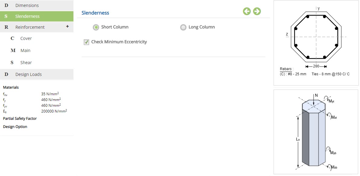
☉Short Column: Select this option to design column as short column.
☉Long Column: Select this option to design column as long column.
☐ Check Minimum Eccentricity
Select this option to consider minimum eccentricity check in the design.
Long Column
In case of long column, user has to provide the following information.
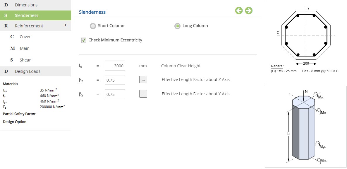 Column Clear Height - Io
Enter the overall height of the column.
↔ Range: 1000 to 20000 mm
Enter effective length factor about Z axis or choose the effective factor from table.
↔ Range: 0.3 to 4
Enter effective length factor about Y axis or choose the effective factor from table.
↔ Range: 0.3 to 4
Slenderness
Clicking on popup button of effective length factor about Z axis or y axis, will open the slenderness popup.
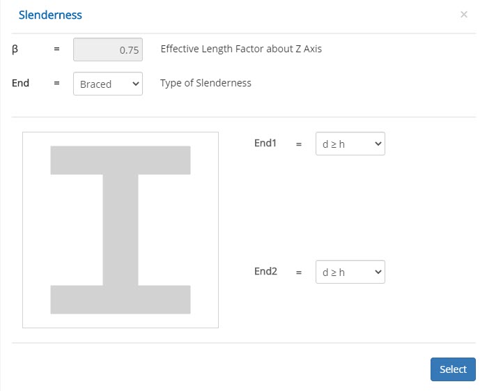 Effective Length Factor about Z Axis - British
Displays the effective length factor about Z axis value based on the selection.
Type of Slenderness
Select the type of slenderness from the drop down.
▽ Braced: Select this option to design the column as a braced member.
▽ Unbraced: Select this option to design the column as a unbraced member.
▽ d ≥ h: The end of the column is connected monolithically to beams on either side which are
at least as deep as the overall dimension of the column in the plane considered. Where the column is connected to a foundation
structure, this should be of a form specifically designed to carry moment.
▽ d < h: The end of the column is connected monolithically to beams or slabs on either side
which are shallower than the overall dimension of the column in the plane considered.
▽ Tie Beam: The end of the column is connected to members which, while not specifically
designed to provide restraint to rotation of the column will, nevertheless, provide some nominal restraint.
▽ Free: The end of the column is unrestrained against both lateral movement and rotation.
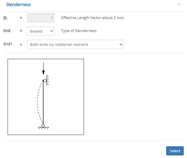 Effective Length Factor about Z Axis - European
Displays the effective length factor about Z axis value based on the selection.
Type of Slenderness
Select the type of slenderness from the drop down.
▽ Braced: Select this option to design the column as a braced member.
▽ Unbraced: Select this option to design the column as a unbraced member.
▽ Both ends no rotational restraint
▽ End 1 no rotational restraint, End 2 rotational restraint
▽ Both ends rotational restraint
▽ Top free, bottom rotational restraint (Cantilever)
▽ Both ends rotational restraint
Cover
This page allows to select cover details for reinforcement.
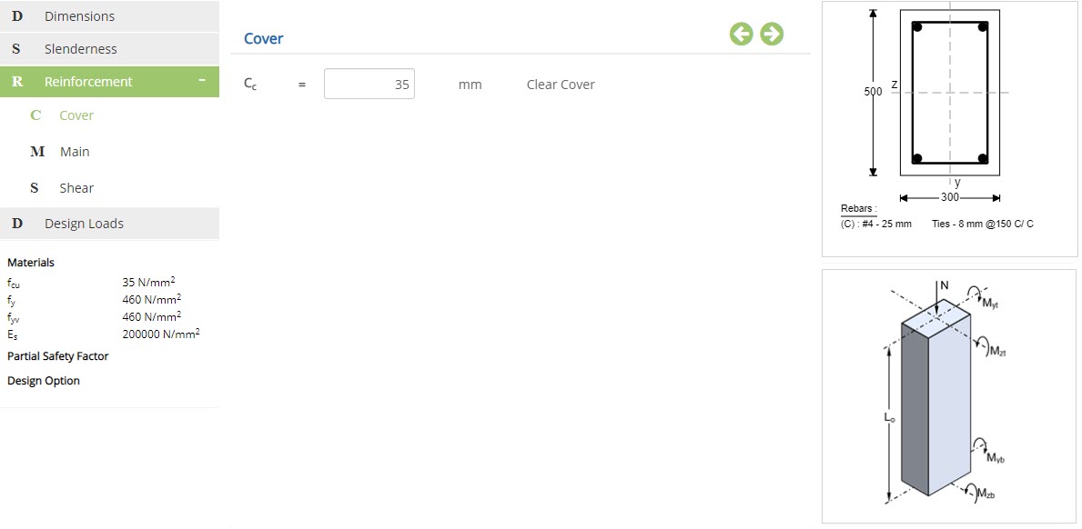 Clear Cover - Cc
Enter the clear cover for reinforcement, if Column Design Option is selected as
Check Reinforcement Adequacy.
↔ Range: 15 to 85 mm
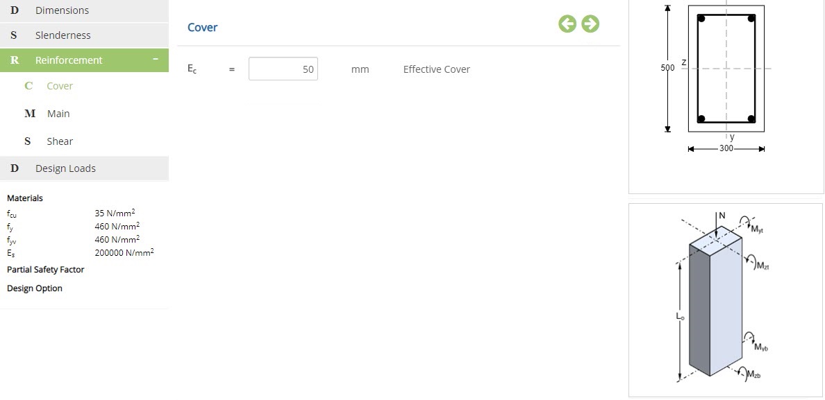 Effective Cover
Enter the effective cover for reinforcement, if Column Design Option is selected as
Find Required Reinforcement.
↔ Range: 15 to 150 mm
Main - Check Reinforcement Adequacy
This page allows to select main reinforcement details, if Column Design Option is selected as Check Reinforcement Adequacy. In this method, moment carrying capacity of the section will be calculated based on the loads and reinforcement details provided.
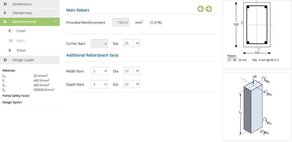
Main Reinforcement - Rectangular Column
Provided ReinforcementShows the area of reinforcement provided based on the rebar configuration.
Corner BarsCorner bars are fixed to 4 numbers.
Dia
Enter or choose the diameter for corner bars.
↔ Range: 4 to 60 mm
Additional Rebars(each face)
Provide the number of bars and diameter for width and depth bars.
Diameter of Bar↔ Range: 4 to 60 mm
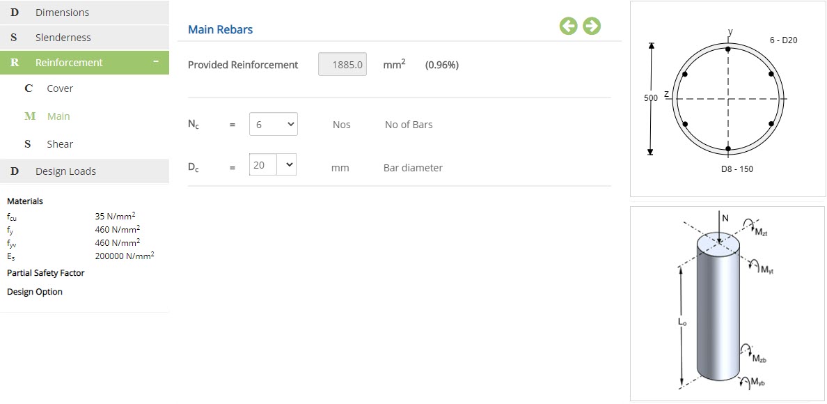
Main Reinforcement - Circular Column
Provided ReinforcementShows the area of reinforcement provided based on the rebar configuration.
No of Bars
Choose the number of main reinforcement bars.
↔ Range: 6 to 15 Nos
Enter or choose the diameter of main reinforcement.
↔ Range: 4 to 60 mm
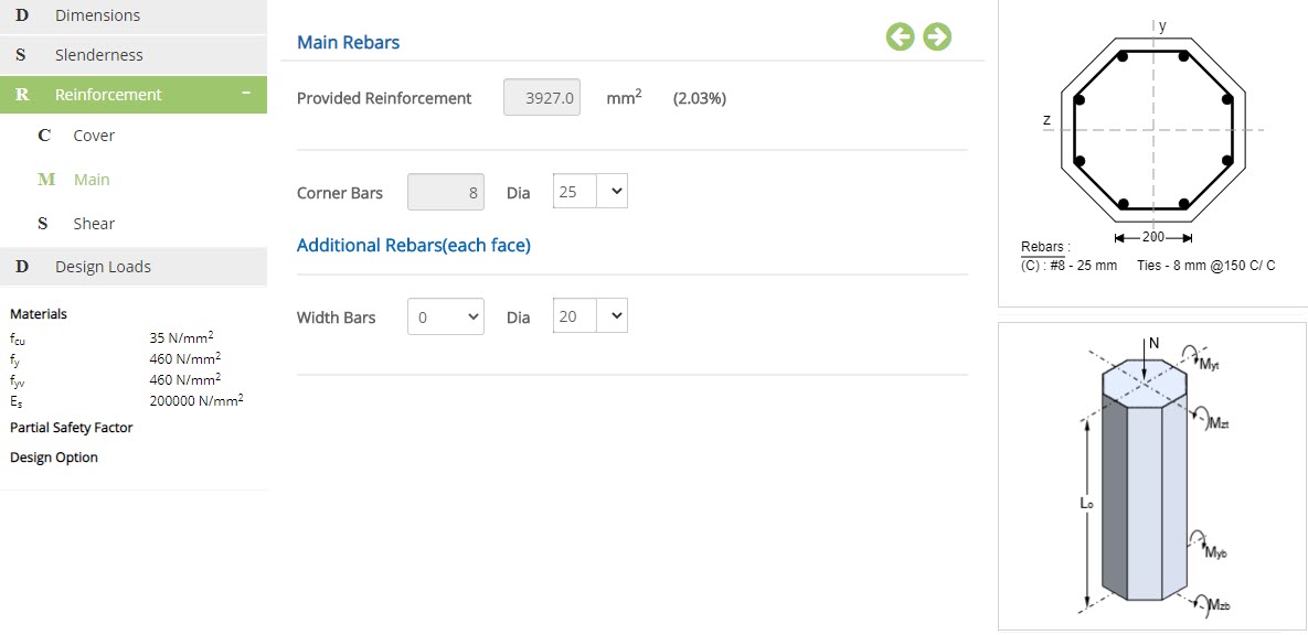
Main Reinforcement - Octagon Column
Provided ReinforcementShows the area of reinforcement provided based on the rebar configuration.
Corner BarsCorner bars are fixed to 8 numbers.
Diameter of Bar
Enter or choose the diameter of main reinforcement.
↔ Range: 4 to 60 mm
Additional Rebars(each face)
Enter or choose number of bars and diameter for width bar.
Main - Find Required Reinforcement
This page allows to select the arrangement of main reinforcement in the column section, if Column Design Option is selected as Find Required Reinforcement. In this method, area of reinforcement required will be calculated.
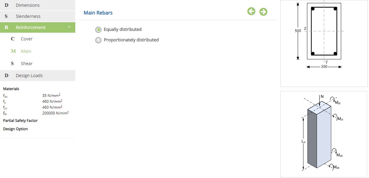
☉Equally distributed: Main reinforcement will be equally distributed over the section for
the design.
☉Proportionately distributed: Main reinforcement will be proportionately distributed over
the section for the design.
Circular Section
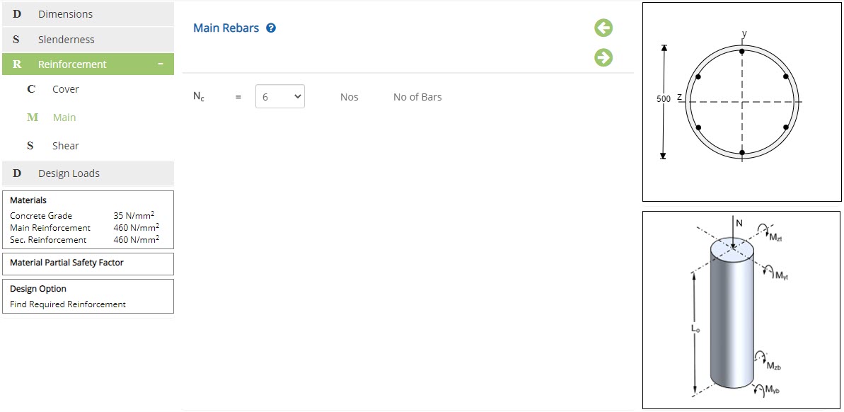 No of Bars
Select the number of bars from the drop down menu.
Shear - Check Reinforcement Adequacy
This page allows to select shear reinforcement details.
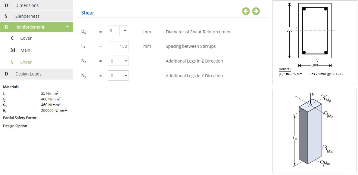
Shear Reinforcement - Rectangular Column
Diameter of Shear Reinforcement - Ds
Enter or choose the diameter of the shear reinforcement.
↔ Range: 4 to 60 mm
Enter the spacing between shear reinforcement.
↔ Range: 20 to 300 mm
Select the number of additional legs to be added in z direction.
Additional Legs in Y Direction - NySelect the number of additional legs to be added in y direction.
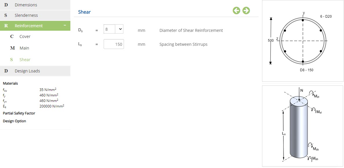
Shear Reinforcement - Circular / Octagonal Column
Diameter of Shear Reinforcement - Ds
Enter or choose the diameter of shear reinforcement.
↔ Range: 4 to 60 mm
Enter the spacing between the stirrups.
↔ Range: 20 to 300 mm
Shear - Find Required Reinforcement
This page allows to select shear reinforcement details, if Column Design Option is selected as Find Required Reinforcement.
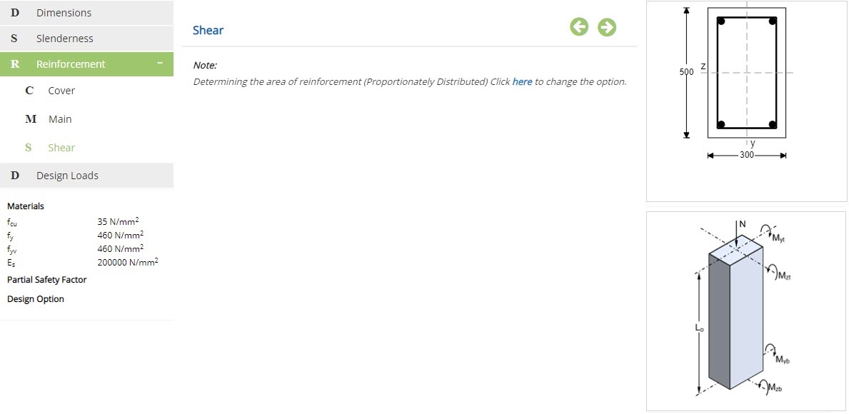
Shear reinforcement details will be applicable in "Check Reinforcement Adequacy" option only.
Design Loads
This page allows to enter design loads. Design loads are entered in an tabular format. This is the menu where we can enter maximum of two combinations for section design.
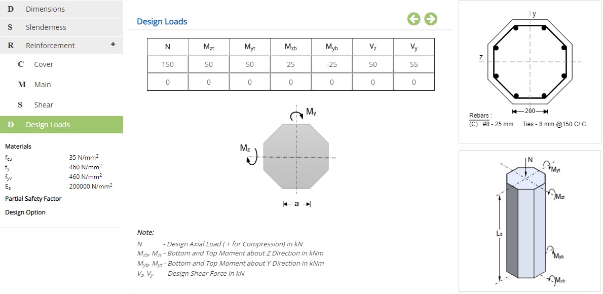 Design Axial Load - N
Enter the design axial load. Positive value indicates compression.
↔ Range: -10000 to 10000 kN
Enter the moment at bottom in z direction.
↔ Range: -10000 to 10000 kNm
Enter the moment at top in z direction.
↔ Range: -10000 to 10000 kNm
Enter the moment at bottom in y direction.
↔ Range: -10000 to 10000 kNm
Enter the moment at top in y direction.
↔ Range: -10000 to 10000 kNm
Enter design shear force in z direction.
↔ Range: -5000 to 5000 kN
Enter design shear force in y direction.
↔ Range: -5000 to 5000 kN
Design Setting
Setting for various Design Data such as Concrete, Reinforcement and Partial Safety Factors are presented in this section. This setting pop-up can be accessed by clicking the bottom panel below the left navigation.
Materials - British
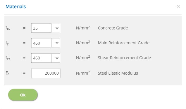 Concrete Grade - fcu
↔ Range: 15 to 100 N/mm2
Main / Shear Reinforcement Grade - fy / fyv↔ Range: 200 to 600 N/mm2
Steel Elastic Modulus - Es↔ Range: 100000 to 300000
Materials - European
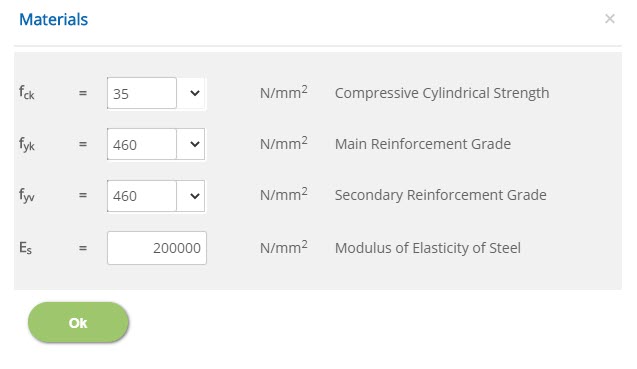 Compressive Cylindrical Strength
↔ Range: 15 to 100 N/mm2
Main / Secondary Reinforcement Grade↔ Range: 200 to 600 N/mm2
Modulus of Elasticity of Steel↔ Range: 100000 to 300000
Material Partial Safety Factor - British
 Concrete in Shear / Concrete in Compression / Reinforcement
γmcs, γmc, γms
↔ Range: 1 to 3
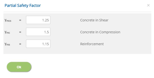
Partial Safety Factor - European
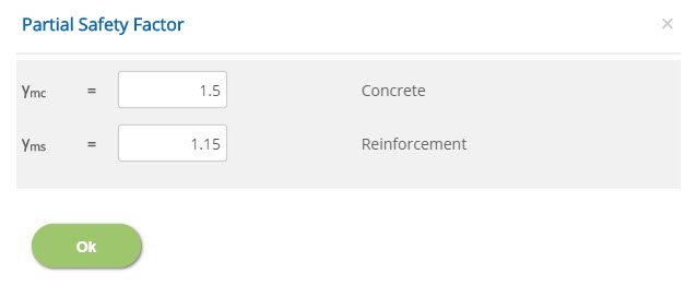 Concrete / Reinforcement
↔ Range: 1 to 3
Column Design Option
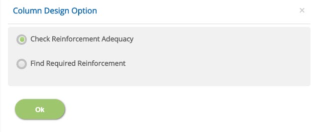
☉Check Reinforcement Adequacy: Select this option for known rebar configuration of the section, hence the program will check the moment.
☉Find Required Reinforcement: Select this option for unknown rebar configuration, hence the program will find the area of reinforcement required for the section.
National Annex - European
This popup allows to select options for national annex in case of European Standard.
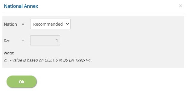 Nation
Select the nation based on which the coefficient value to be considered. The available standards are Recommended, UK, Finland, Ireland, Malaysia, Norway, Singapore, Sweden and User Defined.
User DefinedSelect this option to enter the coefficient values.
αcc↔ Range: 0.7 to 1.2
Error Handling
Errors and Warnings are generated to prevent any inadvertent error in the input data. This section describes how to handle the errors and warnings. These errors are displayed at the bottom of the input page when the data in one or more input fields invalidate each other.
- Note: Out of range errors are displayed next to the input field.
| # | Error | Reason | Solution |
|---|---|---|---|
| 1 | Error : Cover(2 * (Cc + Ds + Dc) + (Nd * Dd)) should be less than breadth. |
Breadth of the column is inadequate to accommodate the given number of bars and cover. | Increase the breadth of the column or decrease the size of bar or cover. |
| 2 | Error : Cover(2 * (Cc + Ds + Dc) + (Nw * Dw)) should be less than depth. |
Depth of the column is inadequate to accommodate the given number of bars and cover. | Increase the depth of the column or decrease the size of bar or cover. |
| 3 | Error : Section height should be greater than 2 x Ec. |
Height of the section is inadequate for the provided effective cover. | Increase the height of the column or decrease the size effective cover. |
| 4 | Error : Section breadth should be greater than 2 x Ec. |
Breadth of the section is inadequate for the provided effective cover. | Increase the breadth of the column or decrease the size effective cover. |
| 5 | Error : Number of bars insufficient for additional legs in Z direction |
Number of bars provided is insufficient for provided additional legs in Z direction. | Provide bars such that the bars and additional legs should be sufficient in Z direction. |
| 6 | Error : Number of bars insufficient for additional legs in Y direction |
Number of bars provided is insufficient for provided additional legs in Y direction. | Provide bars such that the bars and additional legs should be sufficient in Y direction. |
| 7 | Error : Section height should be greater than effective
cover |
Height of the section provided is lesser than the effective cover. | Increase height of the section or decrease the size of effective cover. |
| 8 | Error : All Design Loads cannot be zero. |
All design loads are entered as zero. | A minimum of at least one non-zero design load should be provided. |
| 9 | Error : Reinforcement are Closely Placed. |
Reinforcement bars are placed with an insufficient spacing. | Increase the spacing between reinforcement. |