Help Topics
ECBEAM - Reinforced Concrete Beam Design
This part of user manual describes how to use ECBEAM for the design of REINFORCED CONCRETE BEAM. ECPlus applications are designed as wizard type which is a step by step guided input procedure. If you are new to ECPlus applications, click here for general guidance.
Prerequisites: The user is expected to have a basic understanding of foundation design concepts.
The minimum input data required to use this application is as follows:
- ❶ Dimension and Material Properties
- ❷ Concrete and Reinforcement Grades
- ❸ Allowable safety factors
- ❹ Crack width and its limit
Reinforced Concrete Beam module is available in British, European and American Standards.
Dimensions
This page allows to enter dimensions of the reinforced concrete beam.
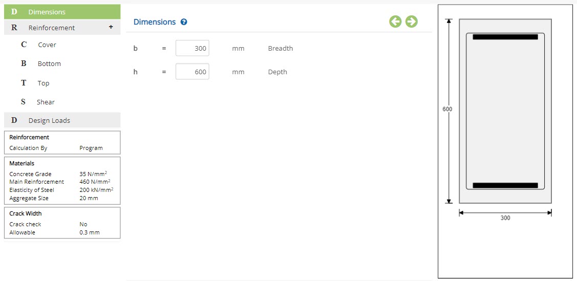 Breadth - b
Enter the breadth of the beam.
↔ Range: 50 to 2500 mm (1 to 100 inches)
Enter the depth of the beam.
↔ Range: 50 to 2500 mm (1 to 100 inches)
Reinforcement
This page allows to enter the reinforcement details such as cover, top, bottom and shear reinforcement details, based on selected Reinforcement Calculation.
Cover
Enter the cover for top and bottom reinforcement.
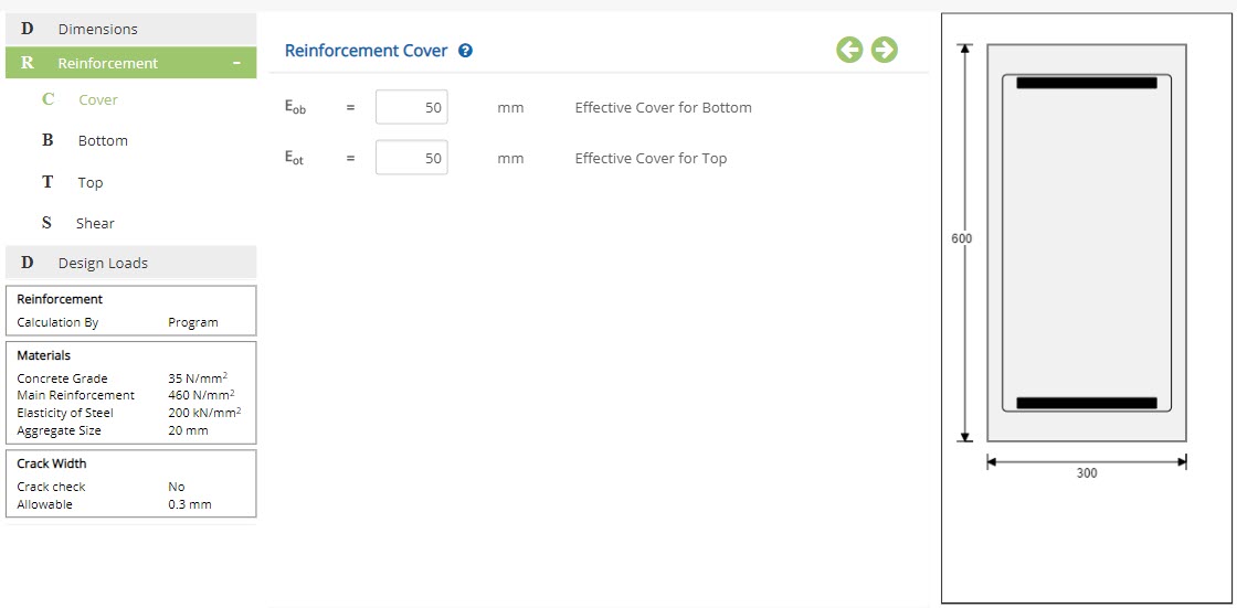
Effective Cover
When Reinforcement Calculation is set to Program or Area , enter the effective cover as input.
Effective Cover for Bottom - EobEnter the effective cover for bottom reinforcement.
↔ Range: 15 to 150 mm (0.6 to 6 inches)
Enter the effective cover for top reinforcement.
↔ Range: 15 to 150 mm (0.6 to 6 inches)
Clear Cover
When Reinforcement Calculation is set to Diameter , enter the clear cover as input.
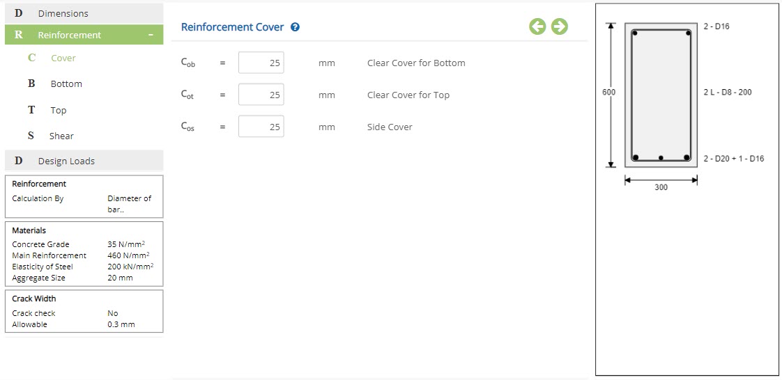 Clear Cover for Bottom - Cob
Enter the clear cover for bottom reinforcement.
↔ Range: 15 to 150 mm (0.6 to 6 inches)
Enter the clear cover for top reinforcement.
↔ Range: 15 to 80 mm (0.75 to 10 inches)
Enter the clear cover for both sides reinforcement.
↔ Range: 15 to 80 mm (0.75 to 10 inches)
Bottom
Enter the reinforcement details for bottom portion.
Bottom - Program
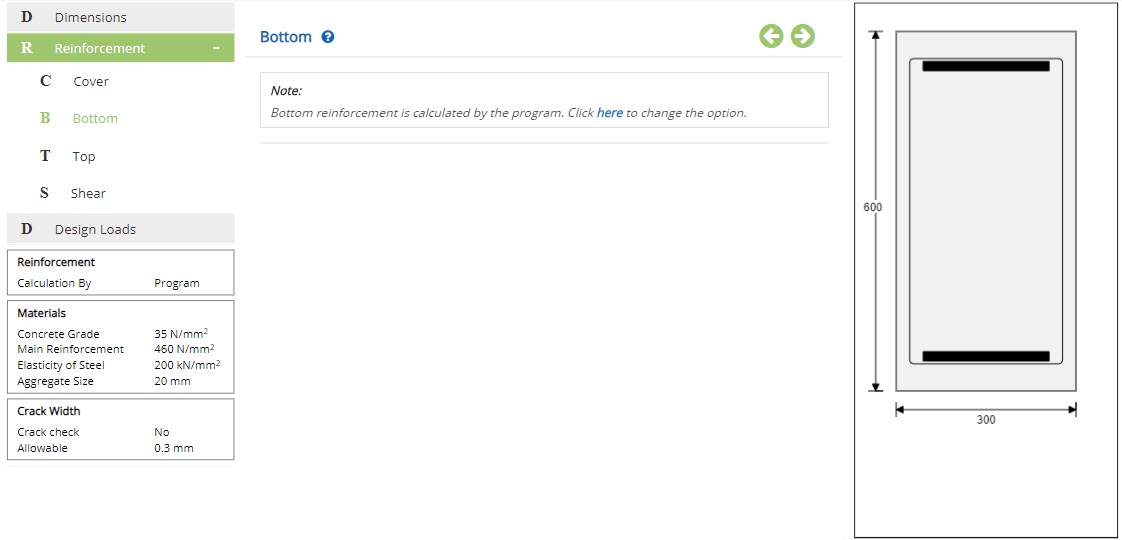
On selecting Reinforcement Calculation as Program , bottom reinforcement required will be calculated by the program, based on the moment applied in the section.
Bottom - Area

On selecting Reinforcement Calculationn as Area , enter the total area of bottom reinforcement.
Area of Bottom Reinforcement - AsbpEnter the total area of bottom reinforcement.
↔ Range: 10 to 500000 mm2 (0.4 to 20000 in2)
Bottom - Diameter
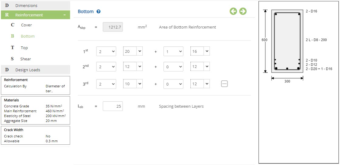
On selecting Reinforcement Calculation as Diameter , provide the number and size for bottom reinforcement.
Number of barsSelect the number of bars from the dropdown.
Size of barSelect the size of bar from the dropdown. Size of bar can also be entered manually.
↔ Range: 4 to 60 mm
If more than one layer of reinforcement are provided, enter the spacing between two layers.
↔ Range: 0 to 100 mm
Reinforcement can be given up to three layers with two different size of bars on each layer.
Top
Enter the reinforcement details for top portion.
Top - Program
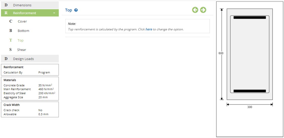
On selecting Reinforcement Calculation as Program , top reinforcement required will be calculated by the program.
Top - Area
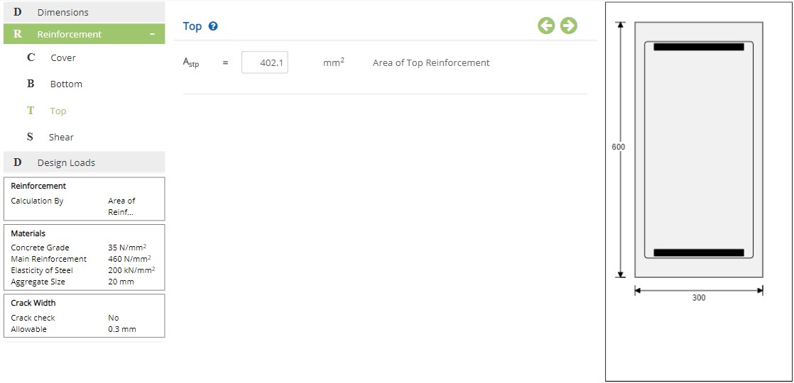
On selecting Reinforcement Calculation as Area , enter the area of top reinforcement.
Area of Top Reinforcement - AstpEnter the total area of top reinforcement.
↔ Range: 10 to 500000 mm2 (0.4 to 20000 in2)
Top - Diameter
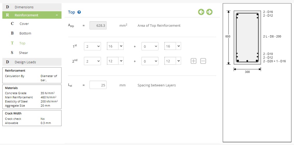
On selecting Reinforcement Calculation as Diameter , select the number and size for top reinforcement.
Number of barsSelect the number of bars from the dropdown.
Size of barSelect the size of bar from the dropdown. Size of bar can also be entered manually.
↔ Range: 4 to 60 mm
If more than one layer of reinforcement are provided, enter the spacing between two layers.
↔ Range: 0 to 100 mm
Reinforcement can be given upto three layers with two different size of bars on each layer.
Shear
Enter the reinforcement details for shear.
Shear - Program
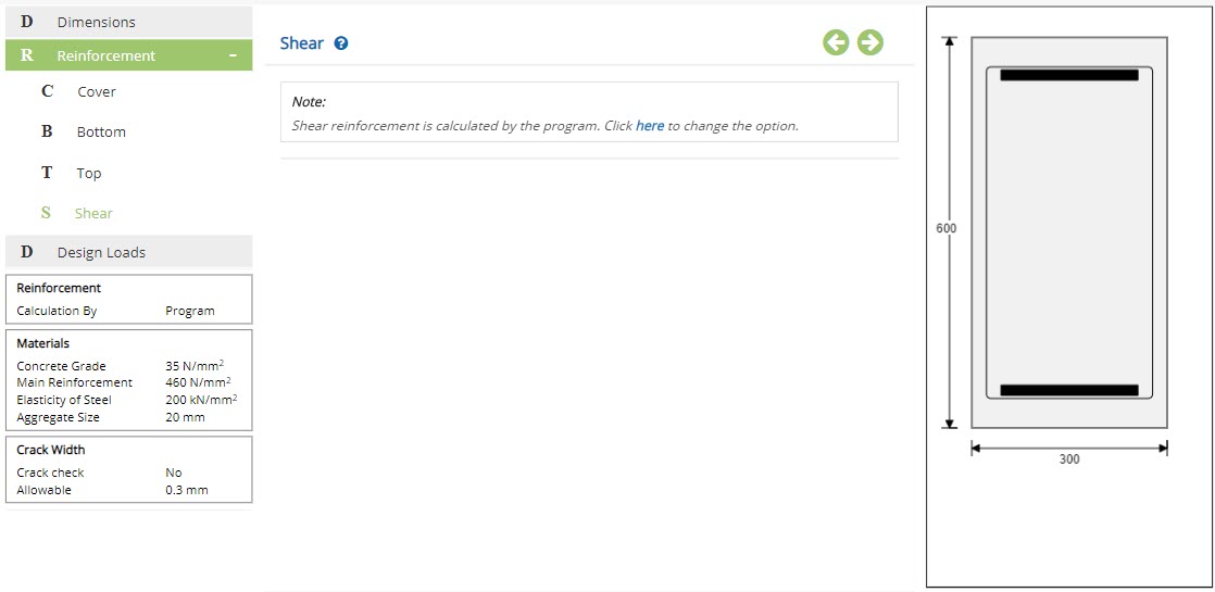
On selecting Reinforcement Calculation as Program , shear reinforcement required will be calculated by the program.
Shear - Area
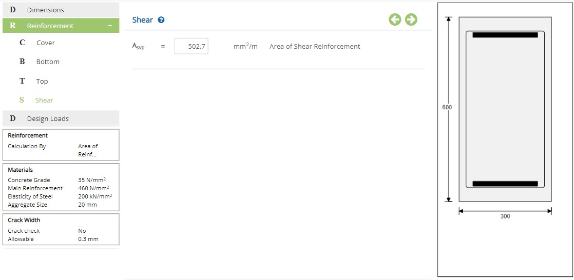
On selecting Reinforcement Calculation as Area , enter the area of shear reinforcement.
Area of Shear Reinforcement - AsvpEnter the total area of shear reinforcement.
↔ Range: 10 to 500000 mm2/m (0.4 to 20000 in2/in)
Shear - Diameter
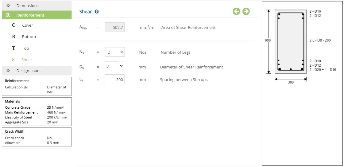
On selecting Reinforcement Calculation as Diameter , select the number of legs, diameter and spacing for shear reinforcement.
Number of Legs - NsSelect the number of bars from the dropdown.
Diameter of Shear Reinforcement - DsSelect the size of bar from the dropdown. Size of bar can also be entered manually.
↔ Range: 4 to 60 mm
Enter the spacing between the consecutive stirrups.
↔ Range: 20 to 450 mm (1 to 20 in)
Design Loads
This page allows to enter the load details such as ultimate shear force, ultimate and service moment for the design.
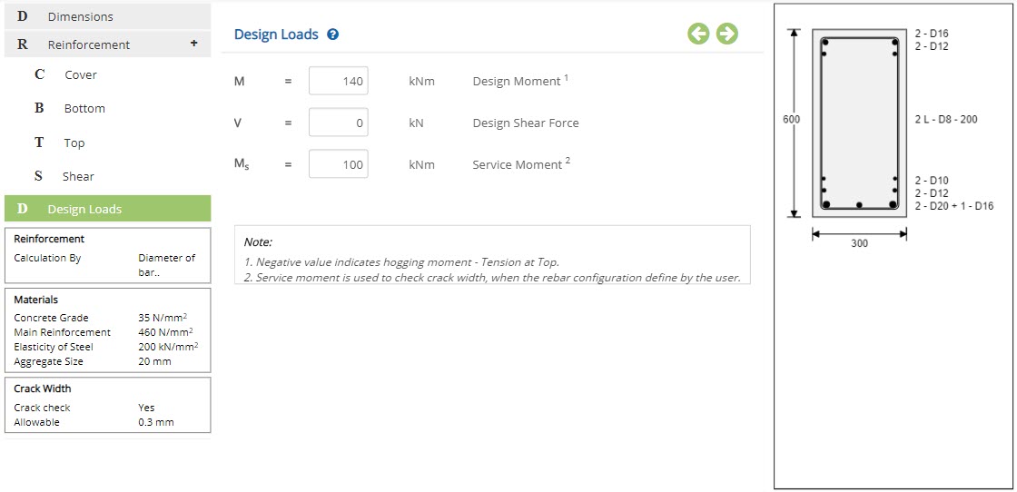 Design Moment - M
Enter the design moment for the calculation of main reinforcement.
↔ Range: -10000 to 10000 kNm (-7000 to 7000 kip-ft)
Enter the shear force for the calculation of shear reinforcement.
↔ Range: 0 to 10000 kNm (0 to 7000 kip-ft)
Enter the service moment for the calculation of crack width. Service moment is enabled only when check for crack width is checked in design setting.
↔ Range: 0 to 10000 kNm (0 to 7000 kip-ft)
Negative value indicates hogging moment.
Design Setting
Setting for various Design Data such as Concrete, Material and Safety Factors are presented in this section. This setting pop-up can be accessed by clicking the bottom panel below the left navigation.
Reinforcement Calculation
This popup allows to set reinforcement calculation method.
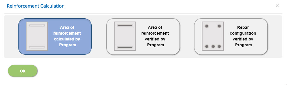
Area of reinforcement calculated by program
Area of reinforcement required will be calculated by the program itself.
Area of reinforcement verified by program
Area of reinforcement required will be calculated by the program and will be checked with the provided reinforcement area.
Rebar configuration verified by program
Area of reinforcement provided will be calculated based on the rebar details and will be verified by the area of reinforcement required calculated by the program.
Materials - British
Enter the various material properties and safety factors in this popup.
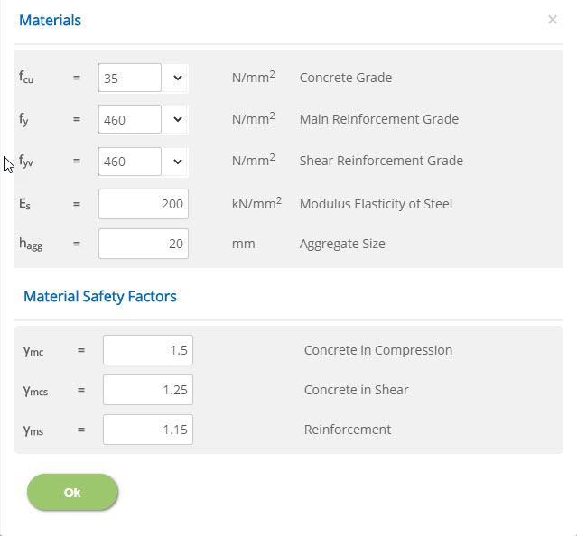 Concrete Grade - fcu
↔ Range: 15 to 100 N/mm2
Main Reinforcement Grade / Shear Reinforcement Grade - fy / fyv↔ Range: 200 to 600 N/mm2
Modulus Elasticity of Steel - Es↔ Range: 50 to 300 kN/mm2
Aggregate Size - hagg↔ Range: 5 to 60 mm
↔ Range: 1 to 3
Concrete in Shear - γmcs↔ Range: 1 to 3
Reinforcement - γms↔ Range: 1 to 3
Materials - European
Enter the various material properties and safety factors in this popup.
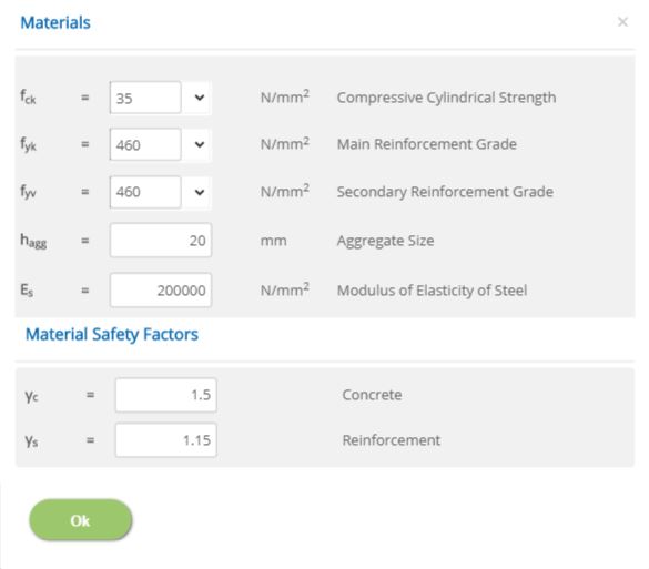 Compressive Cylinder Strength - fck
↔ Range: 12 to 100 N/mm2
Main Reinforcement Grade / Secondary Reinforcement Gradefyk / fyv
↔ Range: 200 to 600 N/mm2
Aggregate Size - hagg↔ Range: 5 to 60 mm
Modulus of Elasticity of Steel - Es↔ Range: 100000 to 300000 N/mm2
Concrete - γc↔ Range: 1 to 3
Reinforcement - γs↔ Range: 1 to 3
Materials - American
Enter the various material properties and safety factors in this popup.
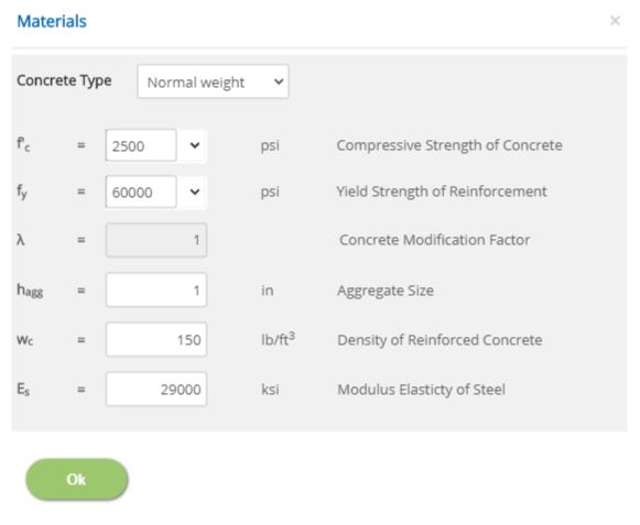 Concrete Type
Select the concrete type from the drop down list from which concrete modification factor will be taken.
Compressive Strength of Concrete - f'c↔ Range: 2500 to 15000 psi
Yield Strength of Reinforcement - fy↔ Range: 40000 to 80000 psi
Concrete Modification Factor - λ↔ Range: 0.75 to 1
Aggregate Size - hagg↔ Range: 0.2 to 2.4 in
↔ Range: 90 to 160 lb/ft3
Modulus Elasticity of Steel - Es↔ Range: 15000 to 40000 ksi
Crack Width
This popup allows to select options for crack width calculation, only on using Diameter as Reinforcement Calculation.
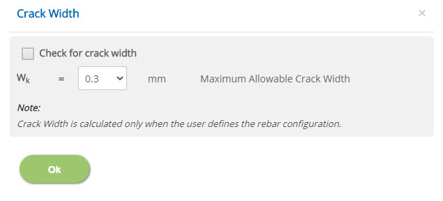
☐ Check for crack width
Enable this option to include crack width check in calculation.
Select the maximum allowable value for crack width in case of British, European and American (Metric) Standards. In case of American (English) Standard, enter the limiting value for crack width.
↔ Range: 0.004 to 0.014 in
Nation Annex
This popup allows to select options for national annex in case of European Standard.
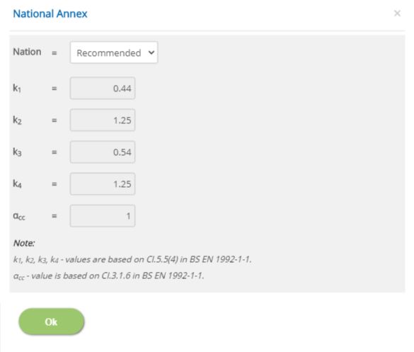 Nation
Select the nation based on which the coefficient value to be considered. The available standards are Recommended, UK, Finland, Ireland, Malaysia, Norway, Singapore, Sweden and User Defined.
User DefinedSelect this option to enter the coefficient values.
k1↔ Range: 0.3 to 0.5
k2↔ Range: 1 to 1.5
k3↔ Range: 0.3 to 0.6
k4↔ Range: 1 to 1.5
αcc↔ Range: 0.7 to 1.2
- Note: Coefficient values are based on BS EN 1992-1-1 codal provisions.
Error Handling
Errors and Warnings are generated to prevent any inadvertent error in the input data. This section describes how to handle the errors and warnings. These errors are displayed at the bottom of the input page when the data in one or more input fields invalidate each other.
- Note: Out of range errors are displayed next to the input field.
| # | Error | Reason | Solution |
|---|---|---|---|
| 1 | Error : Bars are closely placed. Breadth (b) of Section should be greater than sum of effective covers and bar dia in the Layer Note : Applicable for both bottom and top reinforcement and for number of layers provided. | Breadth of the beam is not applicable to place the specified number of bars in the current layer. | Increase breadth of the beam section or decrease cover, diameter or number of bar. |
| 2 | Error : Spacing Between Bar should be greater than maximum of dia bars and hagg Note : Applicable for both bottom and top reinforcement. | Spacing provided between two layers is lesser than either diameter of bar or aggregate size. | Increase Spacing between layers or decrease diameter of bar / aggregate size. |
| 3 | Error : Reinforcement bars are closely placed in section height (h). | Depth of the beam is not applicable to place the specified number of layers in bottom and top reinforcement. | Increase depth of the beam or decrease number of layers and diameter of bar in top or bottom reinforcement. |