Help Topics
ECMONORAIL - Monorail/Runway Beam Design (British)
This section of user manual describes how to use ECMONORAIL for design of Monorail/Runway steel beam. ECPlus applications are designed as wizard type which is a step by step guided input procedure. If you are new to ECPlus applications, click here for general guidance.
Prerequisites: The user is expected to have a general understanding of steel design concepts and its behaviour.
The minimum input data required to use this application is as follows:
- ❶ Monorail Lifting Capacity.
- ❷ Hoist System Vendor Data.
- ❸ Span and Support Conditions.
- ❹ Structural Steel Section and Grade.
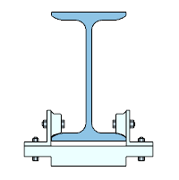
Section
This page allows user to select Monorail member as Standard Hot-rolled or User Defined built-up section.
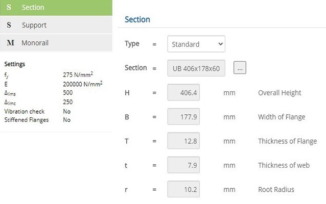
Type
Select the option between Standard or User Defined section.
▽ Standard: Select this option for Monorail to assign as Hot-rolled section as per British, Euro or American Standard.
▽ User Defined: Select this option for Monorail to assign as Built-up Section.
Steel Section Table
By choosing the Type as Standard , the Cross-sectional properties will be displayed for the selected Section. To change the selected Section, click button, a pop-up dialog box displays a list of standard section based on option listed in menu Section Table & Cross Section
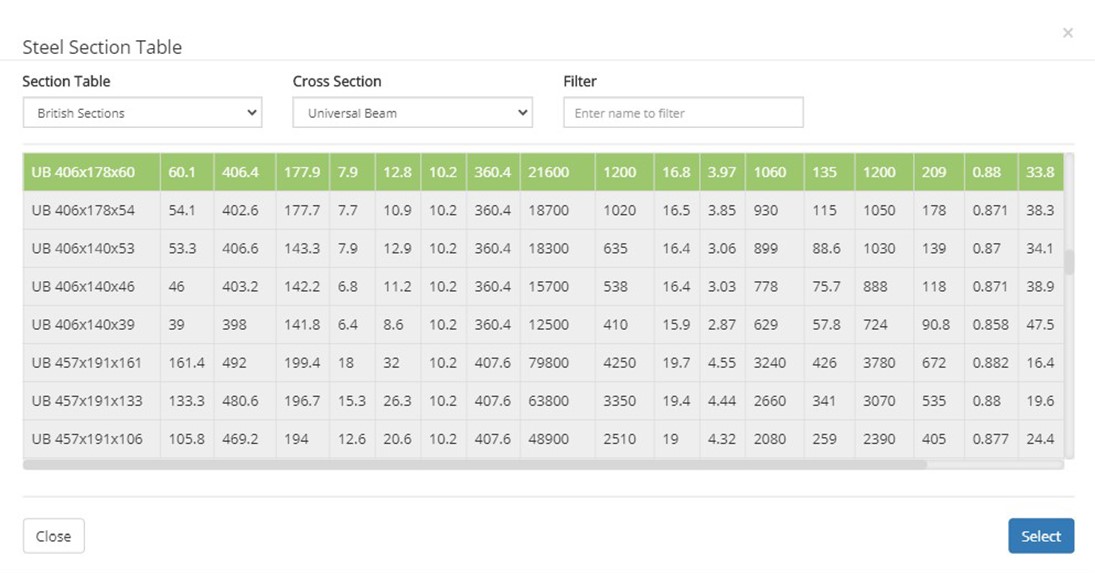 ▽ Section Table:
Select this option to have list of Standard British, European or AISC Sections.
▽ Cross Section:This option allows user to select wider or narrow flange beam like UB, UC, IPE, HE, W, M, etc., based on selection at Section Table menu.
▽ Filter:Based on name by user and with option selected at Section Table and Cross Section , a filtered member list will be displayed.
User Defined Section
User to enter values for overall height, width of flange, thickness of flange and thickness of web. The Sectional Properties for defined member will be calculated by Program.
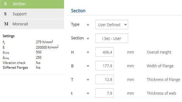
Overall Height
↔ Range: 50 to 1500 mm
Width of Flange
↔ Range: 50 to 1500 mm
Thickness of Flange
↔ Range: 3 to 100 mm
Thickness of Web
↔ Range: 2 to 100 mm
Support
This page allows to enter Monorail beam Span for Simply Supported and Cantilever conditions and selecting Effective Restraint Factor for defined support conditions. Monorail beam shall be designed for following three span scenarios:
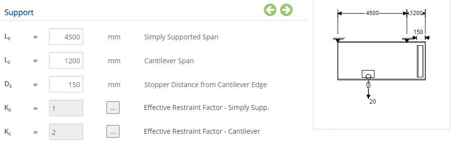 Simply Supported with overhang
Enter value for Ls to define Simply Supported Span and Lc for Cantilever Span, in such case Monorail design will be based on critical moment either as Simply Supported or Cantilever Span.
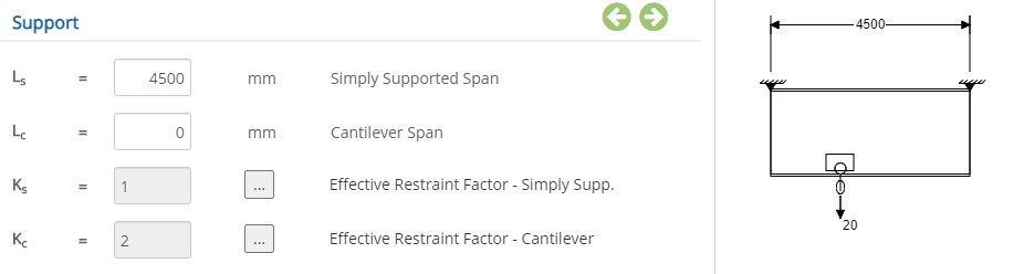 Simply Supported
To design the monorail for Simply Supported condition, enter value for Ls to define Simply Supported Span and Cantilever Span Lc to be set as zero.
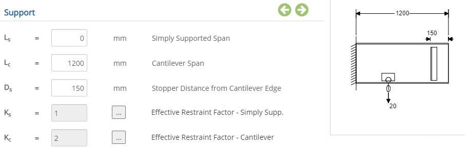 Cantilever
To design the monorail for Cantilever condition, enter value for Lc to define Cantilever Span and Simply Supported Span Ls to be set as zero.
Stopper Distance from Cantilever Edge (Ds)The value indicates the location of stopper from edge of Cantilever beam to limit the movement of Hoist Pulley.
- Note: Stopper distance Ds applicable only for Overhang or Cantilever Support condition.
Simply Supported Span
↔ Range: 0 to 10000 mm
Cantilever Span
↔ Range: 0 to 5000 mm
Stopper Distance from Cantilever Edge
↔ Range: 50 to 5000 mm
Effective Resistance Factor - Simply Supported conditions
Effective Resistance Factor for Simply Supported beam condition shall be selected based on restrained condition for flanges of Monorail beam.
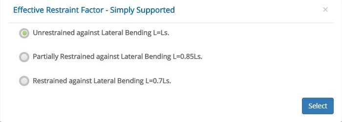
☉ Unrestrained against Lateral Bending L=Ls: When member is unrestrained against lateral bending, the Effective Length will be equal to the span of Simply Supported.
☉ Partially Restrained against Lateral Bending L=0.85Ls: When member is only partially restrained against lateral bending, the Effective Length to be considered as 85 percent of Simply Supported span.
☉ Restrained against Lateral Bending L=0.7Ls: When member is fully restrained against lateral bending, the Effective Length to be considered as 70 percent of Simply Supported span.
Effective Resistance Factor - Cantilever conditions
Effective Resistance Factor for Cantilever beam condition shall be selected based on restrained condition for flanges of Monorail beam.
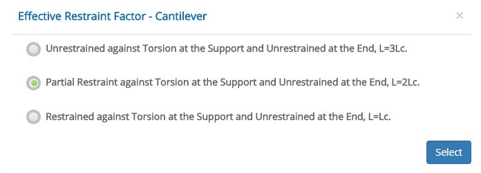
☉ Unrestrained against Torsion at the Support and Unrestrained at the End, L=3Lc: When the member is completely unrestrained against Torsion at support, the Effective Length to be considered as three times of Cantilever span.
☉ Partial Restraint against Torsion at the Support and Unrestrained at the End, L=2Lc: When the member is restrained partially against torsion at support alone, the Effective Length to be considered as two times of Cantilever span.
☉ Restrained against Torsion at the Support and Unrestrained at the End L=0.7Ls: When the member is completely restrained against torsion at support alone, the Effective Length to be considered as equal to Cantilever span.
For all Cantilever conditions the end of beam flange will be fully Unrestrained.
- Note: For beam flange restraint conditions, refer to Code BS2853: 1957
Monorail
This page allows to enter load data for Monorail Capacity, Hoist Pulley Weight and Dynamic Factor for Vertical and Horizontal Loads.
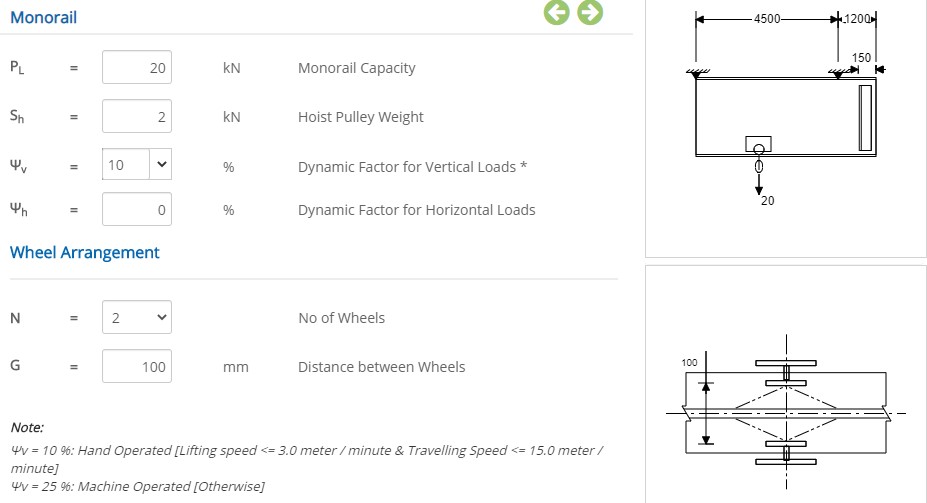
Monorail Capacity
Enter the weight of object to be lifted.
↔ Range: 1 to 50 kN
Hoist Pulley Weight
Enter the weight of Hoist Pulley, includ the weight due to spreader beam arrangement.
↔ Range: 0.1 to 10 kN
Dynamic Factor for Vertical Loads
The factor account for increase in vertical load due to swinging, slipping of slings under accleration or retardation condition during Hoist Pulley movement with lifting load.
The following % increase to be considered if Hoist Pulley gets:
(i) Hand Operated = 10 %.
(ii) Machine Operated = 25 %.
↔ Range: 0 to 100 %
Dynamic Factor for Vertical Loads based on Hand Operated Conditions with lifting and travelling speed limits.
Dynamic Factor for Horizontal Loads
The factor account for increase in Horizontal load due to swinging of loaded slings across the length of Monorail beam.
↔ Range: 0 to 100 %
Wheel Arrangement
User can select Number of wheels, either Two Wheels or Four Wheels based on arrangement of Hoist Pulley assembly.
Number of Wheels - N
N denotes number of wheels in Hoist Pulley assembly, selection of number of wheels shall be based on weight to be lifted and the recommendation from Hoist Pulley supplier.
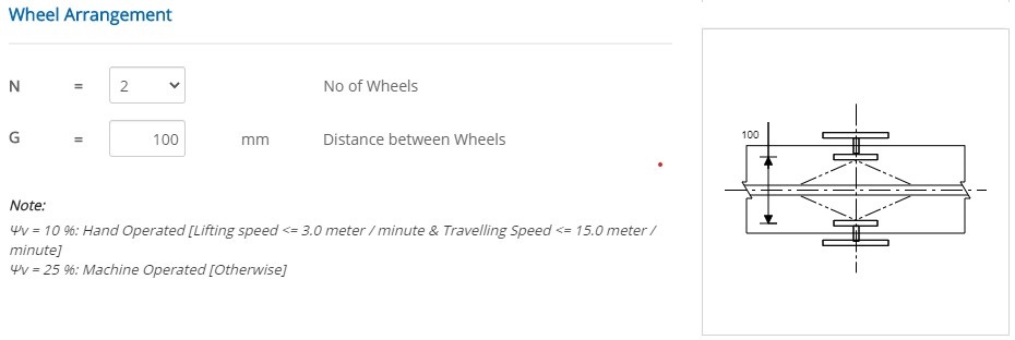
Two Wheel Arrangement
Select the number of wheels (N) as 2.
Distance between Wheels (G)
Enter the spacing between wheels in Hoist Pulley assembly, across the monorail beam length.
↔ Range: 25 to 500 mm
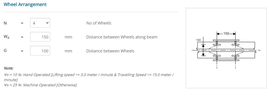
Four Wheel Arrangement
Select the number of wheels (N) as 4.
Distance between Wheels along beam (Wd)
Enter the spacing between wheels in Hoist Pulley assembly, along the monorail beam.
↔ Range: 75 to 350 mm
Setting
Settings for various Design Data such as Steel Grade, Elastic Modulus of Steel and for Serviceability criteria based on support condition. This setting pop-up can be accessed by clicking the bottom panel below the left navigation pane.
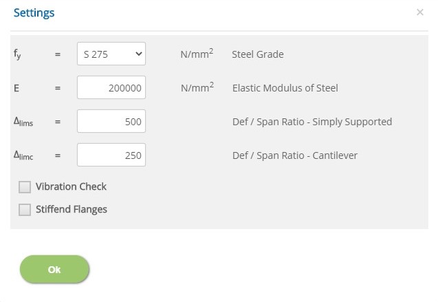
Elastic Modulus of Steel
↔ Range: 100000 to 500000 N/mm2
Deflection Span Ratio for Simply Supported
Δlims - allowable deflection to span ratio for monorail beam in Simply Supported condition.
↔ Range: 200 to 750
Deflection Span Ratio for Cantilever
Δlimc - allowable deflection to span ratio for monorail beam in Cantilever condition.
↔ Range: 200 to 750
☐ Vibration Check: Select this option for optional check to evaluate vibrational capacity of monorail/runway beam as per Euro guidelines.
☐ Stiffened Flanges: Select this option to neglect the failure due to transverse stress occuring at beam end.
Error Handling
Errors are generated to prevent any inadvertent value entries in the input data. This section describes how to handle the errors. These errors are displayed at the bottom of the input page when the data in one or more input fields invalidate each other.
- Note: Out of range errors are displayed next to the input field.
| # | Error | Reason | Solution |
|---|---|---|---|
| 1 | Error : Both Simply Supported and Cantilever span cannot be "0" | Both Simply Supported and Cantilever span are zero. | Value to be greater than "0" for Simply Supported or Cantilever Supported span. |
| 2 | Error : Stopper Edge Distance should be Lesser than Cantilever Span | The Stopper Edge Distance is greater than the Span of Cantilever support. | Increase the Cantilever span or decrease the Stopper Edge Distance. |
| 3 | Error : Distance between Wheels cannot be Greater than Flange Width | The distance between the wheels in Hoist Pulley arrangement is greater than the width of the flange. | Decrease the distance between the wheels or Increase the Flange Width of section. |