Help Topics
ECISOLATED - Isolated Foundation Design
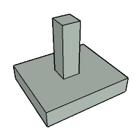
This part of user manual describes how to use ECISOLATED for the design of Isolated Foundations. ECPlus applications are designed as wizard type which is a step by step guided input procedure. If you are new to ECPlus applications, click here for general guidance.
Prerequisites: The user is expected to have a basic understanding of foundation design concepts.
The minimum input data required to use this application is as follows:
- ❶ Soil data such as Safe Bearing Capacity and ground water table.
- ❷ Allowable stability factors
- ❸ Concrete and Reinforcement Grades
- ❹ Pedestal Shape and Dimensions
- ❺ Foundation Loads
Foundation
This page allows to provide the Isolated foundation details and analysis options.
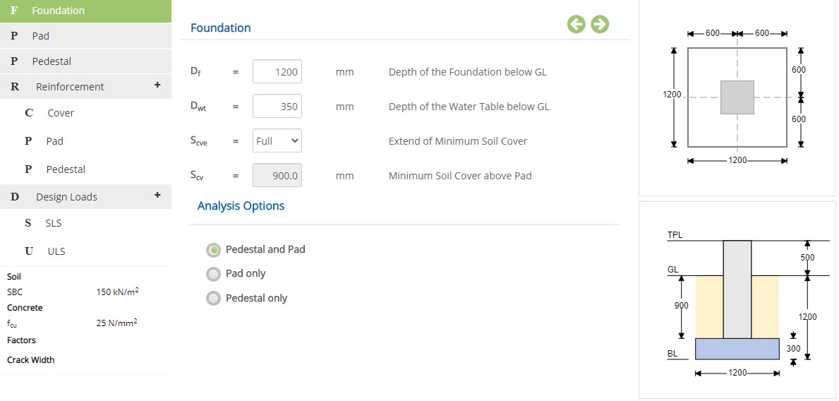 Depth of the Foundation below GL - Df
Enter the depth of the foundation below ground level.
↔ Range: 0 to 6000 mm
Enter the depth of the water table below ground level.
↔ Range: 0 to 5000 mm
▽ Nil: Select this option when there is no soil cover above pad.
▽ Full: Select this option when soil cover is up to ground level above pad.
▽ Partial: Select this option to enter the level of soil cover above pad.
Enter the minimum soil cover above pad, if extend of minimum partial cover is set to partial.
Pedestal and Pad☉ Pedestal and Pad: Select this option to analyse and design both pedestal and pad.
☉ Pad only: Select this option to analyse pad alone.
☉ Pedestal only: Select this option to analyse pedestal alone.
Pad
This page allows to provide dimension of the pad.
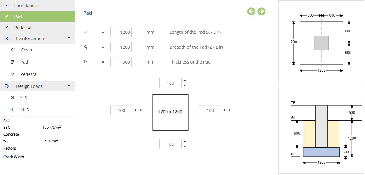 Length of the Pad (X - Dir) - Lf
Enter the length of the pad in X direction.
↔ Range: 300 to 100000 mm
Enter the breadth of the pad in z direction.
↔ Range: 300 to 100000 mm
Enter the thickness of the pad.
↔ Range: 100 to 5000 mm
Size of the pad can also be increased or decreased without affecting the pedestal position by changing the edge distance.
Pedestal
This page allows to enter the pedestal dimension and it's location.
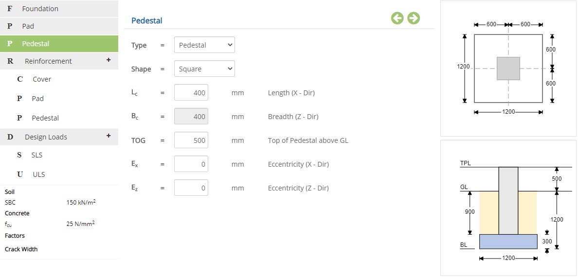
 Type
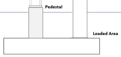
Type▽ Pedestal: Select this option when pedestal load is applied at a height above the ground level such as pedestal supporting a steel column.
▽ Loaded Area: Select this option when pedestal load is applied at the top of the Pad such as a concrete column supporting roof beams.
Select the shape of the pedestal from the available options Rectangular, Square, Circle, Octagon or Wall.
Length (X - Dir) - LcEnter the length of the pedestal for the selected shape as defined in the picture.
↔ Range: 150 to 10000 mm
Enter the breadth of the pedestal for the selected shape as defined in the picture.
↔ Range: 150 to 10000 mm
Enter the diameter of the pedestal, in case of circular pedestal.
↔ Range: 150 to 10000 mm
Enter the height of the pedestal above Ground Level.
↔ Range: -5000 to 5000 mm
Enter the eccentricity for pedestal in X direction from centre of pad.
↔ Range: -600 to 600 mm
Enter the eccentricity for pedestal in Z direction from centre of pad.
↔ Range: -600 to 600 mm
Reinforcement
Cover
This page allows to provide the clear cover for pad and pedestal reinforcements.
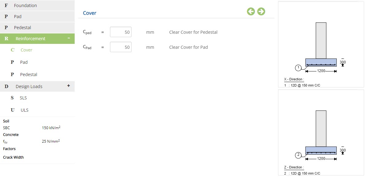 Clear Cover for Pedestal - Cped
Enter the clear cover for pedestal.
↔ Range: 15 to 150 mm
Enter the clear cover for pad.
↔ Range: 15 to 150 mm
Pad
This page allows to provide the reinforcement for pad.
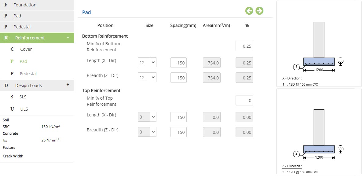 Size
SizeEnter or choose the size of the pad reinforcement in length (X direction) and breadth (Z direction) for both bottom and top layers.
↔ Range: 4 to 60 mm
Enter the spacing of pad reinforcement for both bottom and top layers.
↔ Range: 20 to 450 mm
Displays the area of the pad reinforcement based on size and spacing of bar given for both bottom and top layers.
%Displays the percentage of pad reinforcement provided based on the details provided for both bottom and top layers.
Top reinforcement will not be considered, if minimum % value is provided as zero.
Pedestal
This page allows to provide the reinforcement for pedestal.
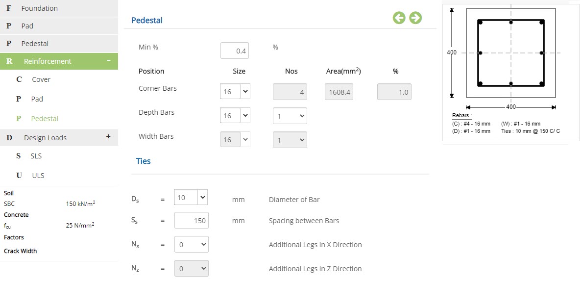 Size
SizeEnter or choose the size of the pedestal reinforcement for corner, depth and width bars.
↔ Range: 4 to 100 mm
Number of corner bars will be fixed (4 Nos) in rectangular or square shape. Additional number of bars can be added in width and depth side.
↔ Range: 0 to 10
↔ Range: 6 to 14 for circular section
Displays the area of reinforcement provided based on size and number of reinforcement provided in the section.
%Displays the percentage of reinforcement provided based on size and number of reinforcement provided in the section.
Diameter of Bar - DsEnter the diameter of ties.
↔ Range: 4 to 60 mm
Enter the spacing between the bars.
↔ Range: 20 to 450 mm
Select the number of additional legs provided in X direction.
Additional Legs in Z Direction - NzSelect the number of additional legs provided in Z direction.
Design Loads
SLS
This page allows to enter the Serviceability limit state (SLS) load details.
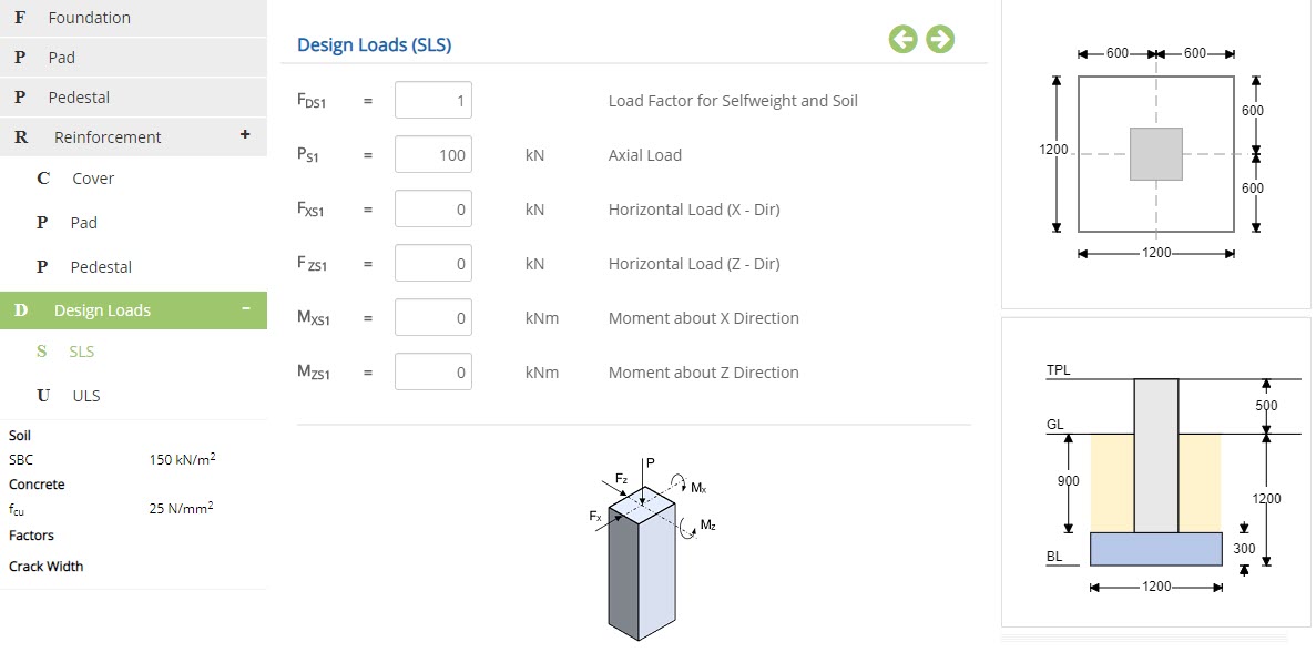 Load Factor for Selfweight and Soil - FDS1
Enter the load factor for self weight and soil loads.
↔ Range: 0 to 5
Enter the axial load.
↔ Range: -10000 to 10000 kN
Enter the horizontal load in X direction.
↔ Range: -10000 to 10000 kN
Enter the horizontal load in Z direction.
↔ Range: -10000 to 10000 kN
Enter the moment in X direction.
↔ Range: -10000 to 10000kNm
Enter the moment in Z direction.
↔ Range: -10000 to 10000 kNm
ULS
This page allows to enter the Ultimate limit state (ULS) load details.
 Load Factor for Selfweight and Soil - FDU1
Enter the load factor for self weight and soil loads.
↔ Range: 0 to 5
Enter the axial load.
↔ Range: -10000 to 10000 kN
Enter the horizontal load in X direction.
↔ Range: -10000 to 10000 kN
Enter the horizontal load in Z direction.
↔ Range: -10000 to 10000 kN
Enter the moment in X direction.
↔ Range: -10000 to 10000kNm
Enter the moment in Z direction.
↔ Range: -10000 to 10000 kNm
Design Setting
Setting for various Design Data such as Soil, Concrete, Safety Factors and Crack Width are presented in this section. This setting pop-up can be accessed by clicking the bottom panel below the left navigation.
Soil
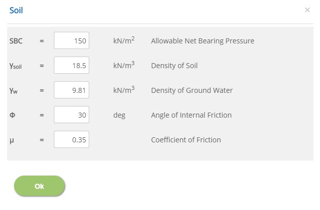 Allowable Net Bearing Pressure - SBC
↔ Range: 50 to 300 kN/m2
Density of Soil - γsoil↔ Range: 16 to 30 kN/m3
Density of Ground Water - γw↔ Range: 5 to 15 kN/m3
Angle of Internal Friction - Φ↔ Range: 0 to 60 deg
Coefficient of Friction - μ↔ Range: 0 to 1
Concrete
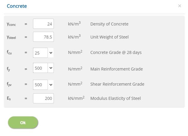 Density of Concrete - γconc
↔ Range: 16 to 30 kN/m3
Unit Weight of Steel - γsteel↔ Range: 50 to 100 kN/m3
Concrete Grade @ 28 days - fcu↔ Range: 15 to 100 N/mm2
Main / Shear Reinforcement Grade - fy / fyv↔ Range: 200 to 600 N/mm2
Modulus Elasticity of Steel - Es↔ Range: 50 to 300 kN/mm2
Factors
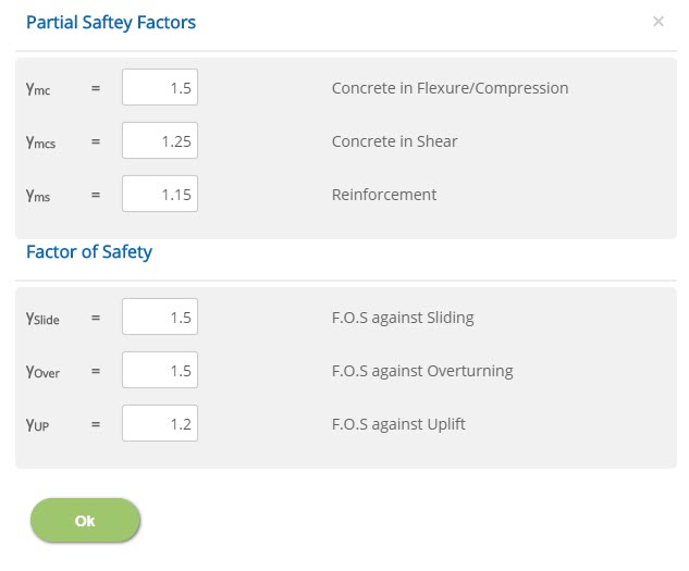 Concrete in Flexure / Compression / Shear - γmc / γmcs
↔ Range: 1 to 2
Reinforcement - γms↔ Range: 1 to 2
F.O.S against Sliding / Overturning / Uplift - γSlide / γOver / γUP↔ Range: 1 to 5
Crack Width
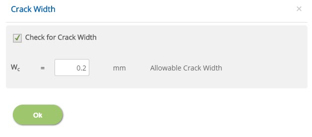
☐ Check for Crack Width
Check this option to include crack width check in the design.
Enter the allowable crack width value.
↔ Range: 0 to 0.4 mm
Error Handling
Errors and Warnings are generated to prevent any inadvertent error in the input data. This section describes how to handle the errors and warnings. These errors are displayed at the bottom of the input page when the data in one or more input fields invalidate each other.
- Note: Out of range errors are displayed next to the input field.
| # | Error | Reason | Solution |
|---|---|---|---|
| 1 | Warning : Top of footing is equal or above grade - soil cover is ignored | Minimum soil cover above pad is greater than zero and thickness of the pad is greater than or equal to depth of the foundation below ground level. | Increase the depth of the foundation below ground level or decrease the thickness of the pad. |
| 2 | Warning : Excess soil cover above grade is ignored | Minimum soil cover above pad is greater than the ground level. | The excess soil cover above ground level will be ignored. |
| 3 | Warning : Length Reinforcement in Bottom should be greater than Minimum Reinforcement | Length reinforcement provided at bottom is insufficient. | Increase the percentage of bottom length reinforcement provided. |
| 4 | Warning : Breadth Reinforcement in Bottom should be greater than Minimum Reinforcement | Breadth reinforcement provided at bottom is insufficient. | Increase the percentage of bottom breadth reinforcement. |
| 5 | Warning : Length Reinforcement in Top should be greater than Minimum Reinforcement | Length reinforcement provided at top is insufficient. | Increase the percentage of top length reinforcement provided. |
| 6 | Warning : Breadth Reinforcement in Top should be greater than Minimum Reinforcement | Breadth reinforcement provided at top is insufficient. | Increase the percentage of top breadth reinforcement. |
| 7 | Warning : Pedestal Reinforcement should be greater than Minimum Reinforcement | Pedestal reinforcement provided for corner bars is insufficient. | Increase the percentage of pedestal reinforcement provided for corner bars. |
| 8 | Error : Insufficient Pedestal Length. Length of Pedestal (Lc) should be greater than Sum of Effective Cover and Bar Dia. | Length of pedestal is lesser than the sum of effective cover and bar diameter. | Increase the length of pedestal or decrease the effective cover or bar diameter accordingly. |
| 9 | Error : Insufficient Pedestal Breadth. Breadth of Pedestal (Bc) should be greater than Sum of Effective Cover and Bar Dia. | Breadth of pedestal is lesser than the sum of effective cover and bar diameter. | Increase the breadth of pedestal or decrease the effective cover or bar diameter accordingly. |
| 10 | Error : Insufficient Pedestal Diameter. Diameter of Pedestal (Dc) should be greater than Sum of Effective Cover and Bar Dia. | Pedestal diameter is lesser than the sum of effective cover and bar diameter. | Increase the diameter of pedestal or decrease the effective cover or bar diameter accordingly. |
| 11 | Error : Number of bars insufficient for additional legs in x direction | Number of bars provided is insufficient for additional legs in x direction. | Increase the number of pedestal bars provided or decrease the number of additional legs provided in x direction. |
| 12 | Error : Number of bars insufficient for additional legs in z direction | Number of bars provided is insufficient for additional legs in z direction. | Increase the number of pedestal bars provided or decrease the number of additional legs provided in z direction. |
| 13 | Error : Thickness of the Pad should be greater than sum of clear cover and diameter of bars | Thickness of the pad provided is insufficient to accommodate provided clear cover and reinforcement. | Increase the thickness of the pad or decrease the clear cover and reinforcement provided. |
| 14 | Error : Pedestal overshoots Pad in X - Direction | Pedestal is located outside the pad in X direction. | Locate the pedestal inside the pad by changing eccentricity in X direction. |
| 15 | Error : Pedestal overshoots Pad in Z - Direction | Pedestal is located outside the pad in Z direction. | Locate the pedestal inside the pad by changing eccentricity in Z direction. |
| 16 | Error : Bottom of Pedestal inside the Pad Thickness | Top of pedestal above ground level lies below top of the pad. | Top of pedestal above ground level should be increased such that it lies above the top of the pad. |