Contents
ECDYN - Technical Reference Manual
Last Updated: December 11, 2020
Version: 1.0
1.0 Introduction
This technical reference presents the theory and general practice for the Dynamic Analysis of Machine foundations using ECDYN. Dynamic Analysis requires more attention since it involves not only the static loads but also the dynamic loads generated due to the Machine operation. The limiting amplitude and operating frequency of a machine are the most important parameters to be considered in analysis of machine foundation.
2.0 Foundation Shapes
ECDYN analyses Rigid Block type foundations which are widely used in the Industry to support Machines such as Centrifugal and Reciprocating Compressors, Pumps and Turbines etc., ECDYN handles any foundation geometry including regular rectangular/square blocks and any other shapes comprises of rectangular/square blocks.
A) Only Block Foundation
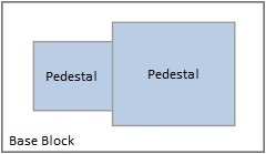
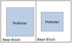
B) Block Foundation with Pedestals
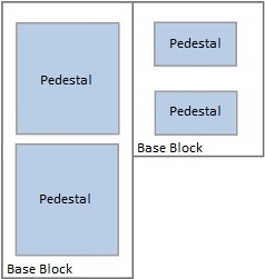
C) Block Foundation with Pedestals having regular Base
D) Block Foundation with Pedestals having any Base like “L”, “T” or varying widths
 |  |  |  |
| (A) | (B) | (C) | (D) |
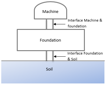
3.0 Machine-Foundation System
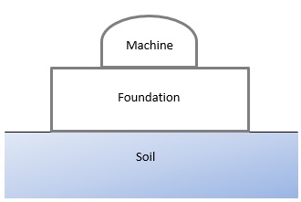
Foundation is considered as a rigid body supported by elastic media. Machine and Foundation are represented as rigid bodies, and Soil is represented as elastic media using equivalent springs. A typical machine foundation system is shown below.
 |
4.0 Basic Principles of ECDYN
Machine foundations shall be designed to cater all the unbalanced dynamic forces of machines which are transmitted to the soil through the foundation in such a way that all kinds of harmful effects are minimized, and the amplitudes of vibration of the machine/foundation are well within the specified limits. In addition, Foundation shall be stable enough to withstand all static and dynamic forces generated by the machine.
The basic principles of ECDYN are
1) No resonance should occur ie., the natural frequency of foundation system shall be away from operating frequency of the machine and shall be within the resonance limits.
2) The amplitudes and velocity due to dynamic (unbalanced) forces shall not exceed the limits.
3) Foundation shall be stable against sliding and overturning.
4) Bearing pressure shall be limited to the allowable value.
5.0 Soil Model
Both Machine and Foundation are represented as rigid bodies and Soil is represented as elastic media using equivalent springs. Under the influence of dynamic forces, the foundation interacts with the soil activating dynamic soil-structure interaction, which significantly influences the dynamic response of machine foundation system. Soil is represented as Equivalent Springs having three Translational and three Rotational stiffnesses attached at the CG of the base of the foundation.
 |
ECDYN requires the below soil parameters and dynamic properties for the machine foundation analysis.
| G | Dynamic Shear modulus (Richard – Lysmer method) |
| ν | Poisson’s ratio |
| γsoil | Soil density |
| D | Soil damping |
| Cu | Coefficients of uniform compression of the soil (Barkan’s Method) |
| Cɸ | Coefficients of non-uniform compression of the soil |
| C𝜏 | Coefficients of uniform shear of the soil |
| CΨ | Coefficients of non-uniform shear of the soil |
| μ | Coefficient of friction |
Irrespective of Analysis Method, User shall provide either G or Cu, and ECDYN calculates the other required soil properties like, & for the Machine foundation analysis.
6.0 Load Cases and Load Combinations
User can provide any number of Load cases and Load combinations, and ECDYN provides full flexibility in combining the loads as per the user’s discretion.
6.1 Dynamic Loads
User shall input the Unbalanced Dynamic force at the rotor location or at the bearing points based on the Vendor provided data. ECDYN transfers these forces to the CG of Base Area for further analysis. In addition, Cyclic loading shall be simulated using Phase angle for Forces and Moments.
6.2 Non-Dynamic Loads
ECDYN auto calculates the Self-weight of the Base Blocks and Pedestals for the analysis. User shall input any Non-Dynamic forces such as Live load, Wind, Seismic, Bearing failure, Short circuit, Blade loss, Torque, Thrust, Rotor removal and Jacking up forces, etc., at user defined locations.
6.3 Service Load Combinations
User shall provide appropriate load factors in line with user’s analysis basis and ECDYN allows the user to populate any number of Load combinations. In addition, it provides wonderful flexibility to the User to increase/decrease the Soil Bearing pressure and change the Stability factors for every load combination.
7.0 Analysis
Machine is relatively rigid compared to foundation and soil and It is considered contributing to mass only with its CG lying above Foundation level.
ECDYN requires the following data to perform the Dynamic Analysis of Machine foundation.
1. Self-weight of Base blocks and Pedestals are auto calculated by the program
2. Weight of the Machine/its parts and its C.G’s
3. Machine operating speeds
4. Dynamic Unbalance Loads and its locations
5. Non-Dynamic Loads such as Wind, Seismic and Loads due to Bearing Failure, Short Circuit and Loss of Blade etc.
There is no limitation on the number of Load cases and Combinations. User can apply both Dynamic and Non-Dynamic loads at any number/location on the Foundation with their correct Co-ordinates.
7.1 Base Eccentricity
ECDYN calculates the eccentricities in plan between the CG of the machine-foundation system and the CG of Base which shall be less than the user provided limit – usually within 5% of the linear dimension of the foundation.
| Description | Formula |
|---|---|
| In X Direction | $$e_x = {x_{base} - x_c\over{X - Dim}} * 100 $$ |
| In Y Direction | $$e_y = {y_{base} - y_c\over{Y - Dim}} * 100 $$ |
7.2 Mass Ratio
ECDYN calculates Mass ratio by comparing mass of foundation with mass of machine. For rotating machines like Centrifugal types, the minimum Mass ratio shall be three times of machine weight whereas it shall be five times of machine weight for reciprocating machines.
| Mass Ratio = Mass of Foundation / Mass of Machine |
7.3 Static Only
ECDYN can be used for machines which don’t require Dynamic analysis. In such cases, user shall provide weight of machine, its C.G’s and Operating Speeds. ECDYN provides checks against Foundation Stability, Base Eccentricity, Mass Ratio and Resonance.
7.4 Resonance
Frequency ratio, the operating speed of the equipment to the natural frequencies of the foundation, is calculated for every translational & rotational modes. Resonance condition occurs when Operating frequency of the machine reaches the Natural frequency of the foundation.
User has flexibility to select the Resonance modes by user selection or based on the forces or for all the modes. ECDYN reports PASS/FAIL against Resonance check for every machine speed based on the user defined frequency range.
| Frequency Ratio = Foundation Frequency / Machine Frequency |
7.5 Amplitude/Velocity
The unbalance dynamic force generated in each rotor may or may not have same Phase Angle for machines having more than one rotor. ECDYN auto generates various possible load groups acting at the user defined load points for In-Phase and Out-of-Phase scenarios based on 90 degree Rotor shift. User shall provide the Phase angle in such a way that Vertical and Horizontal unbalanced dynamic forces shall not be concurrent. For machines with single rotor, ECDYN auto generates all possible load groups acting at user defined load points for all other directions based on 90 degree Rotor shift.
ECDYN transfers all the loads to the common CG of Machine-Foundation system, and provides the Amplitude (zero to Peak) and Velocity of the foundation system based on user’s selection. When user selects “Auto Detect” option, ECDYN automatically detects the maximum Amplitude/Velocity based on the farthest point from Foundation CG . In addition, ECDYN has an option to provide the Amplitude/Velocity of vibration at the “User Defined” locations.
ECDYN reports PASS/FAIL against Amplitude/Velocity by comparing with the user defined permissible limits. User shall repeat the entire analysis by varying the Stiffness, Mass and Damping resistance of the Machine-Foundation system to size the SAFE foundation for the provided machine data.
8.0 Analysis Methods
ECDYN has a facility to analyze the Machine foundation using the following methods.
A. Barkan’s Method (Linear elastic spring theory)
B. Richart-Lysmer’s Method (Elastic Half-Space theory)
User can select any Method to perform the Dynamic Analysis of the Machine foundation.
8.1 Barkan’s Method:
In this method, Foundation is assumed as a rigid lumped mass having infinite stiffness. The effect of Damping is ignored here and the soil is considered as linear weightless springs. Soil is represented by six equivalent springs (three Translational springs and three rotational springs) applied at the CG of the base of the foundation.
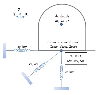
| Notation | Description |
| Jx, Jy and Jz | Mass moment of inertia about common C.G. |
| xc, yc and zc | C.G. of machine and foundation system. |
| Jxbase, Jybase and Jzbase | Mass moment of inertia about base C.G. |
| xbase, ybase and zbase | C.G. of base in X, Y and Z direction. |
| Fx, Fy and Fz | Dynamic force in X, Y and Z direction. |
| Mx, My and Mz | Dynamic moment. |
ECDYN considers the following equivalent soil stiffness at the CG of the Foundation base:
8.1.1 Soil Stiffness
| Description | Formula | Remarks |
|---|---|---|
| In Vertical (Z-Direction) | ${k_z = C_u * Area}$ | Area - Foundation Base Area Ix - Moment of Inertia about X direction Iy - Moment of Inertia about Y direction |
| In Horizontal (X-Direction) | $k_x = C_τ * Area$ | |
| In Horizontal (Y-Direction) | $k_y = C_τ * Area$ | |
| Rotation (about y axis) | ${k_{rx} = C_θ * I_x}$ | |
| Rotation (about x axis) | ${k_{ry} = C_ɸ * I_y}$ | |
| Rotation (about z axis) | ${k_{rz} = C_ψ * ( I_x + I_y )}$ |
8.1.2 Ratio of Mass Moment of Inertia (MMI)
| Direction | Formula | Remarks |
|---|---|---|
| In X Direction | $$r_x = {J_x \over J_{xbase}}$$ | Jx, Jy and Jz - Mass moment of inertia about common C.G. Jxbase, Jybase and Jzbase - Mass moment of inertia about base C.G. |
| In Y Direction | $$r_y = {J_y \over J_{ybase}}$$ | |
| In Z Direction | $$r_z = {J_z \over J_{zbase}}$$ |
| Ratio of MMI = MMI about the common CG of Machine-Foundation system / MMI about the Foundation Base CG |
ECDYN uses the following expressions to calculate the natural frequencies and Amplitudes using the auto generated Load groups as explained above.
Limiting Frequencies are as below:
8.1.3 Undamped Natural Frequency:
| Direction | Formula | Remarks |
|---|---|---|
| Vertical | $$f_z = {\sqrt {k_z \over M_t}}$$ | kx, ky, kz - Equivalent spring constant for rigid foundation Mt - Total mass of machine and foundation system. Jxbase, Jybase and Jzbase - Mass moment of inertia about base C.G. |
| Horizontal (x) | $$f_x = {\sqrt {k_x \over M_t}}$$ | |
| Horizontal (y) | $$f_y = {\sqrt {k_y \over M_t}}$$ | |
| Rotation (about y axis) | $$f_{rx} = {\sqrt {k_{rx} \over J_{xbase}}}$$ | |
| Rotation (about x axis) | $$f_{ry} = {\sqrt {k_{ry} \over J_{ybase}}}$$ | |
| Yawing (about z axis) | $$f_{rz} = {\sqrt {k_{rz} \over J_{zbase}}}$$ |
8.1.4 Uncoupled Modes:
| Direction | Formula | Remarks |
|---|---|---|
| Natural frequency for Vertical translational mode (in Z direction) | $$f_z = \sqrt{k_z \over M_t}$$ | kz and krz - Equivalent spring constant for rigid rectangular foundation Mt - Total mass of machine and foundation system Fz - Dynamic force in Z direction fz - Undamped natural frequency in Z direction fm - Machine frequency Mz - Dynamic moment about Z axis Jz - Mass moment of inertia about common C.G. frz - Undamped natural frequency about Z axis in rotation |
| Vertical Amplitude | $$A_z = {F_z \over M_t * ( {f_z}^2 - {f_m}^2)}$$ | |
| Natural frequency for twisting mode (about Z direction) | $$f_{rz} = \sqrt{k_{rz} \over f_z}$$ | |
| Torsional Amplitude | $$A_{ɸz} = {M_z \over J_z * ( {f_{rz}}^2 - {f_m}^2)}$$ |
8.1.5 Coupled Modes
Natural frequency for Horizontal (Fx) and Rotation (My)| Direction | Formula | Remarks |
|---|---|---|
| Coupled Modes Natural Frequency | $$f_{1rx} = {\sqrt{({f_x}^2 + {f_{ry}}^2 ) + \sqrt{( {f_x}^2 + {f_{ry}}^2 )^2 - 4 * r_y * {f_x}^2 *{f_{ry}}^2 ))} \over 2 * r_y }}$$ $$f_{2rx} = {\sqrt{({f_x}^2 + {f_{ry}}^2 ) - \sqrt{( {f_x}^2 + {f_{ry}}^2 )^2 - 4 * r_y * {f_x}^2 *{f_{ry}}^2 ))} \over 2 * r_y }}$$ | fx - Undamped natural frequency in X direction. fry - Undamped natural frequency about X axis in rotation. rx and ry - Ratio of mass moment of inertia in X and Y direction. xc, yc and zc - C.G. of machine and foundation system. Mt - Total mass of machine and foundation system. fm - Machine frequency. Fx - Dynamic force in X direction. My - Dynamic moment about X axis. Wt - Total weight of machine and foundation system. Jx, Jy and Jz - Mass moment of inertia about common C.G. f1rx and f2rx - Undamped coupled natural frequency in X direction. f1ry and f2ry - Undamped coupled natural frequency in Y direction. Ax - Translational amplitude in X direction. Aɸx - Rotational amplitude in X direction. X, Y and Z - Point of interest for Amplitude / Velocity. |
| Amplitude | $$A_x = {((C_ɸ * I_y - W_t * z_c + C_𝜏 * Area * {z_c}^2 - J_g * {f_m}^2 ) * F_x) - ( C_𝜏 * Area * z_c * M_y) \over M_t * J_y * ({f_{1rx}}^2 - {f_m}^2 ) * ( {f_{2rx}}^2 - {f_m}^2)}$$ $$A_{ɸx} = { (C_𝜏 * Area - W_t * {f_m}^2) * M_y - (C_𝜏 * Area * z_c * F_x) \over M_t * J_y * ({f_{1rx}}^2 - {f_m}^2 ) * ( {f_{2rx}}^2 - {f_m}^2)}$$ $$X Direction = {(A_x + (Z - z_c) * A_{ɸy}) + (Y - y_c) * A_{ɸz}}$$ |
| Direction | Formula | Remarks |
|---|---|---|
| Coupled Modes Natural Frequency | $$f_{1ry} = {\sqrt{({f_y}^2 + {f_{rx}}^2 ) + \sqrt{( {f_y}^2 + {f_{rx}}^2 )^2 - 4 * r_x * {f_y}^2 *{f_{rx}}^2 ))} \over 2 r_x }}$$ $$f_{2ry} = {\sqrt{({f_y}^2 + {f_{rx}}^2 ) - \sqrt{( {f_y}^2 + {f_{rx}}^2 )^2 - 4 * r_x * {f_y}^2 *{f_{rx}}^2 ))} \over 2 r_x }}$$ | fy - Undamped natural frequency in Y direction. frx - Undamped natural frequency about Y axis in rotation. Ay - Translational amplitude in Y direction. Aɸy - Rotational amplitude in Y direction. Aɸz - Rotational amplitude in Z direction. |
| Amplitude | $$A_y = {((C_ɸ * I_x - W_t * z_c + C_𝜏 * Area * {z_c}^2 - J_g * {f_m}^2 ) * F_y) +( C_𝜏 * Area * z_c * M_x) \over M_t * J_x * ({f_{1ry}}^2 - {f_m}^2 ) * ( {f_{2ry}}^2 - {f_m}^2)}$$ $$A_{ɸy} = {(C_𝜏 * Area - W_t * {f_m}^2 ) * M_x) + (C_𝜏 * Area * z_c * F_y) \over M_t * J_x * ({f_{1ry}}^2 - {f_m}^2 ) * ( {f_{2ry}}^2 - {f_m}^2)}$$ $$Y Direction = {(A_y + (Z - z_c) * A_{ɸx}) + (X - x_c) * A_{ɸz}}$$ |
8.2 Richart-Lysmer’s Method (Elastic Half-Space theory)
In this method, Foundation is considered as a lumped mass supported on soil which is idealized as springs in terms of soil parameter “Dynamic Shear Modulus”. Footings having rectangular shape in plan will be converted into a footing having equivalent circular radius to arrive Dynamic properties based on ACI 351.3R.
ECDYN calculates the Dynamic Properties of Machine - Foundation - Soil system based on the expressions shown in the below tables. In this method the embedment coefficients are multiplied to spring constant and damping ratio to get effect of embedment on values of frequency and amplitude.
8.2.1 Equivalent Circular Radius for Rectangular Base
| Direction | Radius Value (m) | Remarks |
|---|---|---|
| In Vertical ( Z - Direction ) | $$r_z = \sqrt {{B_{found} * L_{found}} \over π}$$ | Lfound - Largest dimension of foundation. Bfound - Smallest dimension of foundation (equivalent breadth) Ix - Moment of Inertia about X direction Iy - Moment of Inertia about Y direction |
| In Horizontal ( X or Y - Direction ) | $$r_{xy} = \sqrt {{B_{found} * L_{found}} \over π}$$ | |
| Rotation (about Y axis) | $$r_{rx} = \sqrt[4]{4 * I_y \over π}$$ | |
| Rotation (about X axis) | $$r_{ry} = \sqrt[4]{4 * I_x \over π}$$ | |
| Yawing (about Z axis) | $$r_{rz} = \sqrt[4]{2 * (I_x + I_y) \over π}$$ |
8.2.2 Embedment Coefficients
| Direction | Embedment Coefficients | Remarks |
|---|---|---|
| In Vertical ( Z - Direction ) | $$η_z := 1 + 0.6 * (1 - v) * {h \over r_z} $$ | v - Poisson ratio of soil h - Embedment Depth rz, rxy, rrx, rry & rrz - Equivalent circular radius for rectangular base. |
| In Horizontal ( X or Y - Direction ) | $$η_{xy} := {1 + 0.55 * (2 - v)} * {h \over r_{xy}}$$ | |
| Rotation (about Y axis) | $$η_{rx} := 1 + 1.2 * (1 - v) * ({h \over r_{rx}}) + 0.2 * (2 - v) * ({h \over r_{rx}})^3 $$ | |
| Rotation (about X axis) | $$η_{ry} := 1 + 1.2 * (1 - v) * ({h \over r_{ry}}) + 0.2 * (2 - v) * ({h \over r_{ry}})^3 $$ |
8.2.3 Mass Ratio
| Direction | Mass Ratio | Remarks |
|---|---|---|
| In Vertical ( Z - Direction ) | $$B_z := {(1 - v) \over 4} * {M_t * g \over γ_{soil} * {r_z}^3}$$ | g - Gravity acceleration γsoil - Density of soil |
| In Horizontal ( X or Y - Direction ) | $$B_{xy} := {7 - 8 * v \over 32 * (1 - v)} * {M_t * g \over γ_{soil} * {r_{xy}}^3}$$ | |
| Rotation (about Y axis) | $$B_{rx} := {3 * (1 - v) \over 8} * {J_y \over γ_{soil} * {r_{rx}}^5}$$ | |
| Rotation (about X axis) | $$B_{ry} := {3 * (1 - v) \over 8} * {J_x \over γ_{soil} * {r_{ry}}^5}$$ | |
| Yawing (about Z axis) | $$B_{rz} := {J_z \over {γ_{soil}} * {r_{rz}}^5}$$ |
8.2.4 Damping Ratio Embedment Factor
| Direction | Damping Ratio Embedment Factor | Remarks |
|---|---|---|
| In Vertical ( Z - Direction ) | $$α_z : = {1 + 1.9 * (1 - v)* h \over { r_z * \sqrt η_z}}$$ | ηz, ηxy, ηrx and ηrz - Embedment coefficients |
| In Horizontal ( X or Y - Direction ) | $$α_{xy} : = {1 + 1.9 * (1 - v)* h \over { r_{xy} * \sqrt η_{xy}}}$$ | |
| Rotation (about Y axis) | $$α_{rx} : = {1 + 0.7 * (1 - v)* {h \over r_{rx}} + 0.6 * (2 - v) * ({h \over r_{rx}})^3 \over \sqrt η_{rx}}$$ | |
| Rotation (about X axis) | $$α_{ry} : = {1 + 0.7 * (1 - v)* {h \over r_{ry}} + 0.6 * (2 - v) * ({h \over r_{ry}})^3 \over \sqrt η_{ry}}$$ |
8.2.5 Damping Ratio
| Direction | Soil Damping | Remarks |
|---|---|---|
| In Vertical ( Z - Direction ) | $$D_{z} := min({0.425 \over \sqrt{B_z}} * α_z, D_{zmax})$$ | Bz, Bxy and Brx - Mass Ratio αx, αy, αz, αxy, αrx and αry - Damping Ratio Embedment Factor Dzmax, Dxymax, Drxmax, Drymax and Drzmax - Maximum damping ratio based on ACI 351 3R or user defined |
| In Horizontal ( X or Y - Direction ) | $$D_{xy} : = min({0.288 \over \sqrt{B_{xy}}} * α_{xy}, D_{xymax})$$ | |
| Rotation (about Y axis) | $$D_{rx} := min({0.15 \over (1 + η_{rx} * B_{rx}) * \sqrt {η_{rx} * B_{rx}}} * α_{rx}, D_{rxmax})$$ | |
| Rotation (about X axis) | $$D_{ry} := min({0.15 \over (1 + η_{ry} * B_{ry}) * \sqrt {η_{ry} * B_{ry}}} * α_{ry}, D_{rymax})$$ | |
| Yawing (about Z axis) | $$D_{rz} := min({0.5 \over 1 + 2 * B_{rz}}, D_{rzmax})$$ |
8.2.6 Coefficients βz, βx and βΨ for rectangular footings:
Coefficients based on Bfound / Lfound or Lfound / Bfound ratio
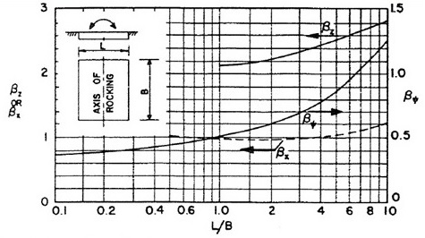
Subscripts denote the following:
"βz" - motion along Z axis
"βx" - motion along X axis
"βy" - motion along Y axis
"βrx" - rotation about Y axis
"βry" - rotation about X axis
8.2.7 Equivalent spring Constant for Rigid Rectangular Foundation
| Direction | Spring Value (kN/m, kN*m/rad) | Remarks |
|---|---|---|
| In Vertical ( Z - Direction ) | $$k_z := {G_s \over 1 - ν} * β_z * \sqrt {B_{found} * L_{found}} * η_z$$ | Gs - Dynamic shear modulus βx, βy, βz, βrx and βry - Coefficients based on breadth to length ratio |
| In Horizontal ( X or Y - Direction ) | $$k_x := 2 * (1 + ν) * G_s * β_x * \sqrt {B_{found} * L_{found}} * η_{xy}$$ | |
| Rotation (about Y axis) | $$k_{rx} := {G_s \over 1 - ν} * β_{rx} * L_{found} * {B_{found}}^2 * η_{rx}$$ | |
| Rotation (about X axis) | $$k_{ry} := {G_s \over 1 - ν} * β_{ry} * B_{found} * {L_{found}}^2 * η_{ry}$$ | |
| Yawing (about Z axis) | $$k_{rz} := {16 * G_s * {r_{rz}}^3 \over 3}$$ |
8.2.8 Damping Constant for Rigid Rectangular Foundation
| Direction | Damping Constants (kN/(m/s), kN*m/(rad/s)) | Remarks |
|---|---|---|
| In Vertical ( Z - Direction ) | $$C_z := 2 * D_z * \sqrt{k_z * M_t}$$ | Dz, Dxy, Drx, Dry and Drz - Damping ratio kx, ky, kz, krx, kry and krz - Equivalent spring constant for rigid rectangular foundation |
| In Horizontal ( X or Y - Direction ) | $$C_x := 2 * D_{xy} * \sqrt{k_x * M_t}$$ $$C_y := 2 * D_{xy} * \sqrt{k_y * M_t}$$ | |
| Rotation (about Y axis) | $$C_{rx} := 2 * D_{rx} * \sqrt{k_{rx} * J_y}$$ | |
| Rotation (about X axis) | $$C_{ry} := 2 * D_{ry} * \sqrt{k_{ry} * J_x}$$ | |
| Yawing (about Z axis) | $$C_{rz} := 2 * D_{rz} * \sqrt{k_{rz} * J_z}$$ |
8.2.9 Undamped Natural Frequencies
| Direction | Frequency Value (rad/sec) | Remarks |
|---|---|---|
| In Vertical ( Z - Direction ) | $$f_z := \sqrt{k_z \over M_t}$$ | kz - Equivalent spring constant for rigid rectangular foundation Mt - Total mass of machine and foundation system αx, αy, αz, αxy, αrx and αry - Damping Ratio Embedment Factor |
| In Horizontal ( X or Y - Direction ) | $$f_x := \sqrt{k_x \over M_t}$$ $$f_y := \sqrt{k_y \over M_t}$$ | |
| Rotation (about Y axis) | $$f_{rx} := \sqrt{k_{rx} + M_t * z_c \over J_y + M_t * {z_c}^2}$$ | |
| Rotation (about X axis) | $$f_{ry} := \sqrt{k_{ry} + M_t * z_c \over J_x + M_t * {z_c}^2}$$ | |
| Yawing (about Z axis) | $$f_{rz} := \sqrt{k_{rz} \over J_z}$$ |
8.2.10 Undamped Coupled Natural Frequencies
| Direction | Frequency Values (rad/sec) | Remarks |
|---|---|---|
| Horizontal (Fx) and My | $$f_{1rx} := \sqrt {{{f_{rx}}^2 + {f_x}^2 + \sqrt {({f_{rx}}^2 + {f_x}^2)^2 - 4 * α_y * {f_{rx}}^2 * {f_x}^2}}\over 2 * α_y}$$ $$f_{2rx} := \sqrt {{{f_{rx}}^2 + {f_x}^2 - \sqrt {({f_{rx}}^2 + {f_x}^2)^2 - 4 * α_y * {f_{rx}}^2 * {f_x}^2}}\over 2 * α_y}$$ | fx and fy - Undamped natural frequency in X and Y direction frx, fry - Undamped natural frequency about Y and X axis in rotation αx and αy are as follows $$α_x := {J_x \over {J_x + M_t * {z_c}^2}}$$ $$α_y := {J_y \over {J_y + M_t * {z_c}^2}}$$ |
| Horizontal (Fy) and Mx | $$f_{1ry} := \sqrt {{{f_{ry}}^2 + {f_y}^2 + \sqrt {({f_{ry}}^2 + {f_y}^2)^2 - 4 * α_x * {f_{ry}}^2 * {f_y}^2}} \over 2 * α_x}$$ $$f_{2ry} := \sqrt {{{f_{ry}}^2 + {f_y}^2 - \sqrt {({f_{ry}}^2 + {f_y}^2)^2 - 4 * α_x * {f_{ry}}^2 * {f_y}^2}} \over 2 * α_x}$$ |
8.2.11 Time History Analysis
ECDYN performs Time History Analysis based on the damped system using Wilson θ Method. Pseudo dynamic forces are calculated using Transmissibility factors and the Machine speed, and provide Amplitude/Velocity at the point of interest.
Amplitude in horizontal (Fx) coupled with Rocking/Pitching (My) mode| $\begin{bmatrix} M_t & 0 \\ 0 & J_y \end{bmatrix}$ * $\begin{bmatrix} X_{fx}'' \\ X_{my}'' \end{bmatrix}$ + $\begin{bmatrix} C_x & -C_x * z_c \\ -C_x * z_c & C_{my} + C_x * {z_c}^2 \end{bmatrix}$ * $\begin{bmatrix} X_{fx}' \\ X_{my}' \end{bmatrix}$ + $\begin{bmatrix} k_x & -k_x * z_c \\ -k_x * z_c & k_{my} + k_x * {z_c}^2 \end{bmatrix}$ * $\begin{bmatrix} X_{fx} \\ X_{my} \end{bmatrix}$ = $\begin{bmatrix} F_x & 0 \\ 0 & M_y \end{bmatrix}$ * $\begin{bmatrix} sin(f_m * t + ɸ_{fx}) \\ sin(f_m * t + ɸ_{my}) \end{bmatrix}$ |
| $\begin{bmatrix} M_t & 0 \\ 0 & J_x \end{bmatrix}$ * $\begin{bmatrix} X_{fx}'' \\ X_{my}'' \end{bmatrix}$ + $\begin{bmatrix} C_y & -C_y * z_c \\ -C_y * z_c & C_{mx} + C_y * {z_c}^2 \end{bmatrix}$ * $\begin{bmatrix} X_{fx}' \\ X_{my}' \end{bmatrix}$ + $\begin{bmatrix} k_y & -k_y * z_c \\ -k_y * z_c & k_{mx} + k_y * {z_c}^2 \end{bmatrix}$ * $\begin{bmatrix} X_{fx} \\ X_{my} \end{bmatrix}$ = $\begin{bmatrix} F_y & 0 \\ 0 & M_x \end{bmatrix}$ * $\begin{bmatrix} sin(f_m * t + ɸ_{fx}) \\ sin(f_m * t + ɸ_{my}) \end{bmatrix}$ |
| $M_t * X_{f_z}'' + C_z * X_{f_z}' + K_z * X_{fz} = F_z * sin(f_m * t + ɸ_{fz})$ |
| $J_z * X_{mz}'' + C_{rz} * X_{mz}' + K_{mz} * X_{mz} = M_z * sin(f_m * t + ɸ_{mz})$ |
| fm | Machine frequency | |
| ɸfx, ɸfy and ɸfz | Phase angle of forces | |
| ɸMx, ɸMy and ɸMz | Phase angle of moments |
| Displacement: $X_r = \sqrt{{X_{fx}}^2 + {X_{fy}}^2 + {X_{fz}}^2}$ |
| Velocity: $X'_r = \sqrt{{X'_{fx}}^2 + {X'_{fy}}^2 + {X'_{fz}}^2}$ |
| Notation | Description |
| Mt | Total mass of machine and foundation system |
| Cx, Cy, Cz, Crx, Cry and Crx | Damping constant for rigid rectangular foundation |
| kx, kz, krx, kry and krz | Equivalent spring constant for rigid rectangular foundation |
| Fx * sin(fm * t + ɸfx), Fy * sin(fm * t + ɸfy), Mx * sin(fm * t + ɸmx) | Forcing functions at the C.G. of machine-foundation system |
8.2.12 Wilson θ method
ECDYN uses Wilson θ method to carry out Time History analysis. In this method, Acceleration is assumed to be linear from time “t” to “t+Δt”, with θ greater than or equal to one (1). ECDYN follows the below procedure to perform this analysis.
Initial Calculation1) Mass Matrix [M], Stiffness Matrix [K] and Damping Matrix [C] are to be formed.
2) Initialize Xt, X't, X''t at t = 0.
3) Integration constant θ = 1.4 (usually).
| θ = 1.4 | Δt = degree steps / ( 6 x maximum machine speed(rpm)) |
| α0 = 6 / (θ * Δt)2 | α5 = -α2 / θ |
| α1 = 3 / (θ * Δt) | α6 = 1 - 3 / θ |
| α2 = 2 * α1 | α7 = Δt / 2 |
| α3 = θ * Δt / 2 | α8 = Δt2 / 6 |
| α4 = α0 / θ |
4) From effective stiffness matrix [Keff] = [K] + α0 * [M] + a1 * [C]
For each time step1) Effective loads at time t + Δt
Rt + θ * Δt = Rt + θ * (Rt + Δt - Rt) + M * (α0 * Xt + α2 * X't + 2 * X"t) + C * (α1 * Xt + 2 * X't + α3 * X"t)
2) Xt + θ * Δt = Keff-1 * Rt + θ * Δt
3) Calculate displacements, velocities and accelerations at time t + Δt
X"t + Δt = α4 * (Xt + θ * Δt - Xt) + α5 * X't + α6 * X"t
X't + Δt = X't + α7 * (X"t + Δt + X"t)
Xt + Δt = Xt + Δt * X't + α8 * (X" t + Δt + 2 * X"t)
8.2.13 Graphs
Based on the user provided degree steps, ECDYN calculates the number of Time steps to perform Time history analysis and plot graphs for Amplitude/Velocity for every time steps at the user defined location or at critical locations at every level.
| Time step (Δt) = degree steps / ( 6 * maximum machine speed(rpm)) |
9.0 Stability Analysis
ECDYN carry out Stability analysis such as Soil Bearing pressure check, Sliding and Overturning check for the user defined load cases and load combinations.
9.1 Soil Bearing Pressure
ECDYN adopts linear soil pressure distribution as the Foundation is Rigid Block type.
Soil overburden on top of Base block is considered is the analysis. When the water table is present within the foundation depth, buoyancy effect is considered as below:
| Uplift load = (Water table Height * Density of Water) * Base Area |
This uplift load is deducted from the total vertical load.
The base pressure at four corners is then calculated as
| $$p_i = {P \over A} ± {(M_x + P * e_y) \over z_x} ± {(M_y + P * e_x) \over z_y}$$ |
Where ex and ey are eccentricities of total vertical load in X and Y directions. It shall be noted that foundation shall be stable against overturning to determine the bearing pressure.
9.2 Sliding
Stability of the foundation against sliding (movement of Foundation due to lateral forces) depends on total vertical loads and the frictional factor between the Base block and soil. Soil weight and buoyancy effect is considered to arrive at the total vertical loads.
Factor of safety against sliding| $$FOS = {P * μ \over F_v}$$ |
μ - Friction Factor
Fv - Resultant Shear Force = [Fx2 + Fy2]1 / 2
9.3 Overturning
Stability of the foundation against overturning is provided by the total vertical loads on the foundation. Soil weight and buoyancy effect is considered to arrive at the total vertical loads.
Factor of safety against overturning in each axis (X and Y):| $$FOS = Resisting Moment / Overturning Moment$$ |
Where,
Resisting Moment about X and Y = P * Cgy and P * Cgx
Mx and My - Overturning Moment about X and Y
Cgx and Cgy - The centre of gravity of vertical loads from overturning edges
The passive pressure components on pedestals and base blocks will be included in the overturning resistance.