Help Topics
ECDYN - Dynamic Foundation Design
This part of user manual describes how to use ECDYN analysis of Dynamic Foundation. ECPlus applications are designed as wizard type which is a step by step guided input procedure. If you are new to ECPlus applications, click here for general guidance.
Prerequisites: The user is expected to have basic understanding on Analysis of Dynamic foundation.
The minimum input data required to use this application is as follows:
- ❶ Soil and Dynamic Criteria.
- ❷ Allowable stability factors.
- ❸ Base Block and Machine Component details.
- ❹ Dynamic and Non-dynamic Loading.
Technical reference for ECDYN can be found here.
Following sections are presented with various input pages of ECDYN application with descriptions:Analysis Options
This page allows to select Dynamic Analysis Method, Time History Chart Type for Report and Unit.
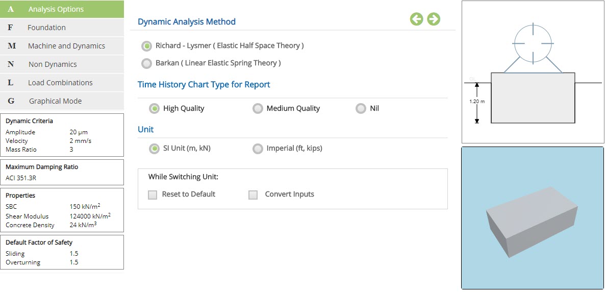
Dynamic Analysis Method
Select the method for the dynamic analysis.
☉Richard - Lysmer ( Elastic Half Space Theory ) : Select this option to use Richard method for the dynamic analysis.
☉Barkan ( Linear Elastic Spring Theory ) : Select this option to use Barkan method for the dynamic analysis.
Time History Chart Type for Report
☉High Quality : Select this option to generate time history chart in higher quality.
☉Medium Quality : Select this option to generate time history chart in medium quality.
☉Nil : Select this option, if time history chart is not needed.
Unit
☉SI Unit (m, kN) : Select this option to proceed with SI units.
☉Imperial (ft, kips) : Select this option to proceed with Imperial units.
While Switching Unit:
☐ Reset to Default : Select this option to reset all values with default values, on switching between units using above option.
☐ Convert Inputs : Select this option to convert the input values, on switching between units using above option.
- Note: Time History Chart Type for Report is applicable only for Richard - Lysmer (Elastic Half Space Theory).
Foundation
This page allows to select the input of foundation data such as Depth of the Foundation and Embedment.
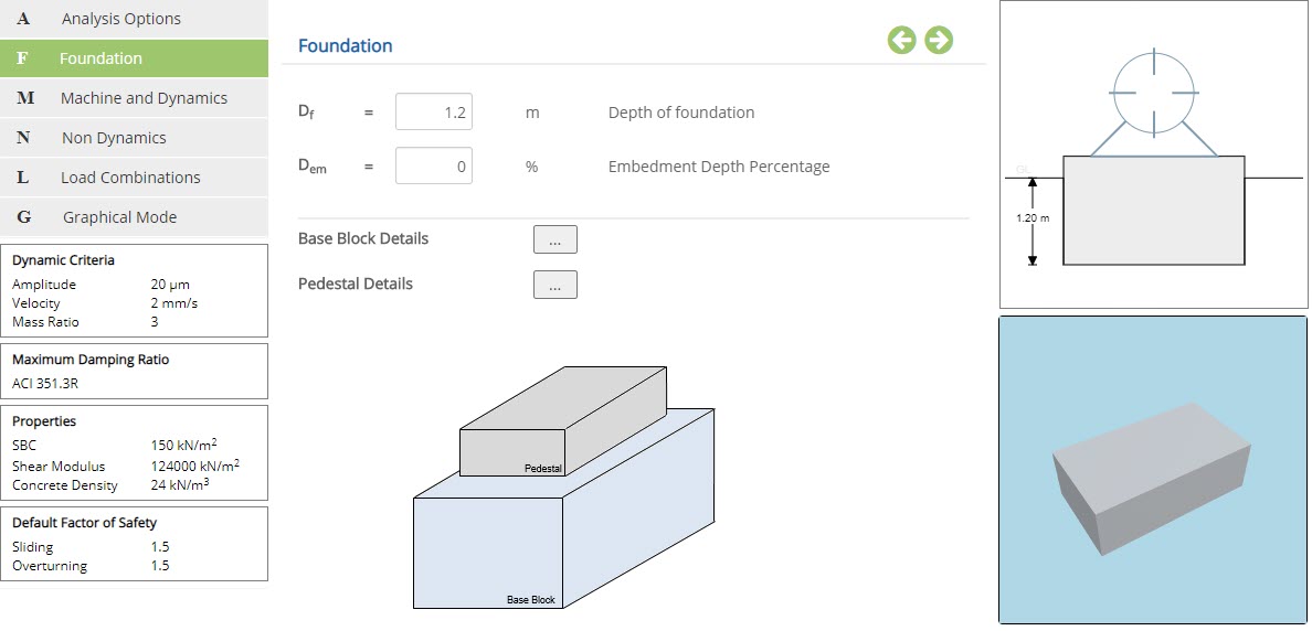 Depth of Foundation
Enter the overall depth of the foundation.
↔ Range: 0 to 10 m
Enter the percentage depth of embedment of the base block in to the soil.
↔ Range: 0 to 100 %
The buttons Base Block Details and Pedestal Details are provided in this section.
Base Block Details
Click this button to open the pop-up dialog to define the base block and its dimensions. This is a spreadsheet type input dialog - right click on the spreadsheet to add or delete rows. Alternatively, the user can copy and paste data from an external source such as Microsoft Excel.
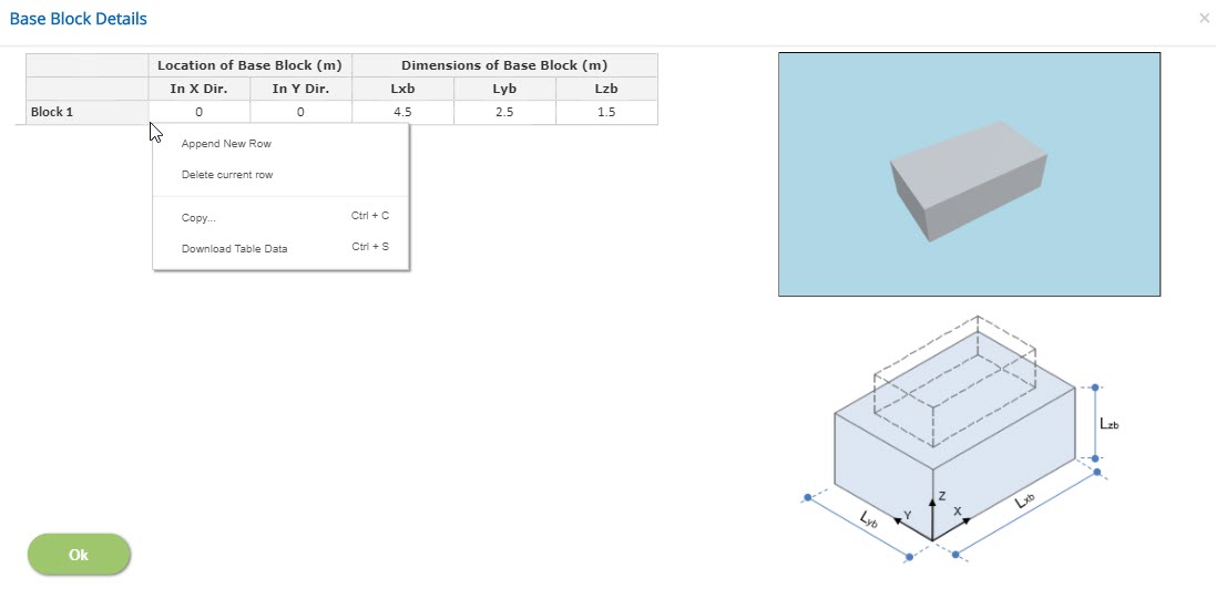
Location of Base Block
Enter the location of base block corresponding to X and Y directions from origin.
Dimensions of Base Block
Enter the dimensions of the base block.
Base block in X direction (Lxb)↔ Range: 0.1 to 100 m
Base block in Y direction (Lyb)↔ Range: 0.1 to 100 m
Depth of the base block (Lzb)↔ Range: 0.2 to 10 m
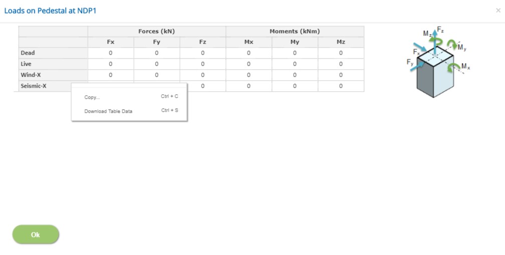
Pedestal Details
Click this button to open the pop-up dialog to define the dimension and location of pedestals. This is a spreadsheet type input dialog - right click on the spreadsheet to add or delete rows. Alternatively, the user can copy and paste data from an external source such as Microsoft Excel.
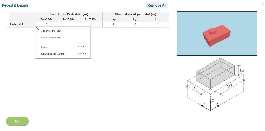
Dimensions of pedestal
Pedestal dimension in X direction (Lxp)Enter the pedestal dimension in X direction.
↔ Range: 0 to 100 m
Enter the pedestal dimension in Y direction.
↔ Range: 0 to 100 m
Enter the depth of the pedestal.
↔ Range: 0 to 10 m
Location of Pedestal
Enter the location of pedestal corresponding to X, Y and Z directions from origin.
- Note: Default option is to have base block only, in order to remove all input data in case of no pedestal available, use 'Remove All' button.
Machine and Dynamics
This page allows to provide the machine and dynamics data.
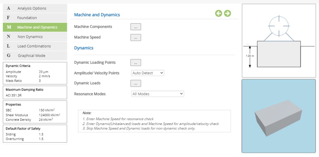
Machine and Dynamics
The buttons Machine Components and Machine Speed are provided in this section.
Dynamics
The following buttons are provided as a pop-up dialog for the input data:
- Dynamic Loading Points
- Amplitude / Velocity Points
- Dynamic Loads
Machine Components
Click this button to open the pop-up dialog to define the machine components. This is a spreadsheet type input dialog - right click on the spreadsheet to add or delete rows. Alternatively, the user can copy and paste data from an external source such as Microsoft Excel.
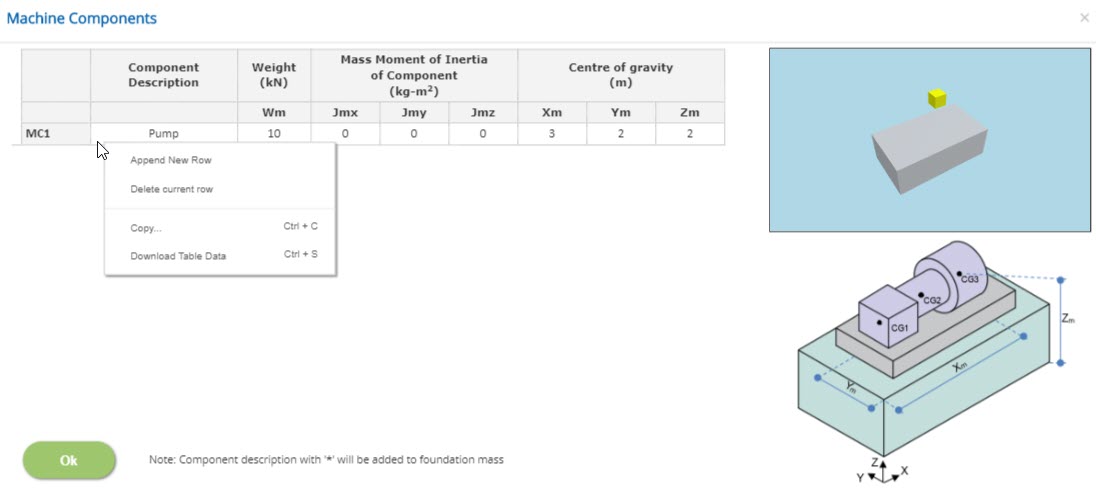
Component Description
Enter the name of the machine component such as pump, motor, etc.,
Weight
Enter the weight of the machine component.
↔ Range: 0.1 to 10000 kN
Mass Moment of Inertia of Machine Component
Enter the mass moment of inertia of machine in X, Y and Z directions.
↔ Range: 0 to 10000 kg-m2
Centre of Gravity
Enter the centre of gravity of the machine component corresponding to X, Y and Z directions from origin.
- Note: Component description with '*' marked in its name will be added to foundation mass.
Machine Speed
Click this button to open the pop-up dialog to define the machine speed. This is a spreadsheet type input dialog - right click on the spreadsheet to add or delete rows. Alternatively, the user can copy and paste data from an external source such as Microsoft Excel.
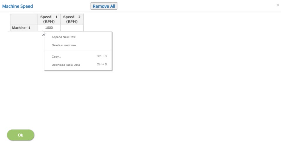
Constant Speed
If the machine is of constant speed type, the speed should be entered in Speed-1. Entering speed data in speed-1 column alone will consider the machine runs in a constant speed.
Variable Speed
If the machine runs at variable speeds, then speed data should be entered in corresponding columns. A maximum of ten speeds for a single machine can be given as an input.
↔ Range: 50 to 25000 RPM
- Note: If machine speed which has been used at dynamic loads is deleted, it will be deleted at dynamic loads also.
Dynamic Loading Points
Click this button to open the Dynamic Loading Points pop-up dialog. This is a spreadsheet type input dialog but rows cannot be deleted or added. The user can copy and paste the data from an external source such as Microsoft Excel.
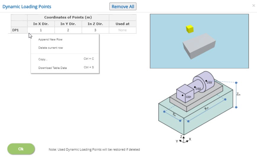
Coordinates of Points
Enter the X, Y and Z coordinates from the origin at which the dynamic load is acting.
Used at
Displays the dynamic load which is acting at the corresponding location.
- Note: Any dynamic loading point which has been used for dynamic loads cannot be deleted. If any used dynamic loading point row is deleted, it will be restored after the pop-up is closed.
Amplitude / Velocity Points
Click this button to open the Amplitude / Velocity Points pop-up dialog. This is a spreadsheet type input dialog but rows cannot be deleted or added. The user can copy and paste the data from an external source such as Microsoft Excel.
▽ Auto Detect: Amplitude / Velocity points will be auto detected by considering farthest point from the CG of the foundation system.
▽ User Defined: Selecting this option and use popup button to enter Amplitude / Velocity points.
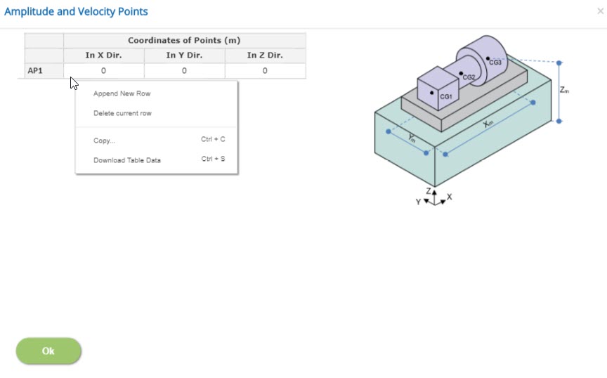
Coordinates of Points
Enter the X, Y and Z coordinates value from the origin at which the amplitude/velocity is to be calculated.
Dynamic Loads
Click this button to open the dynamic loads pop-up dialog. This is a spreadsheet type input dialog but rows cannot be deleted or added. The user can copy and paste the data from an external source such as Microsoft Excel.
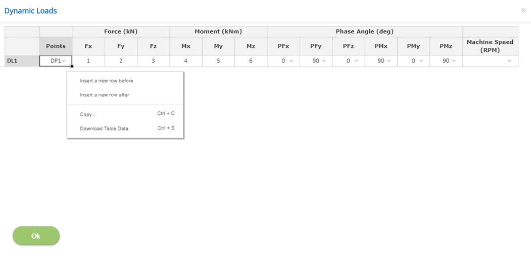
Points
List of dynamic loading points defined will be displayed in a drop down box. Select the point at which the corresponding loads are acting.
Forces
Enter the forces acting in the selected loading point in corresponding X, Y and Z directions.
↔ Range: -100000 to 100000 kN
Moment
Enter the moments acting in the selected loading point in corresponding X, Y and Z directions.
↔ Range: -100000 to 100000 kNm
Phase Angle
Select Phase angle (0 or 90 degree) for the Forces and Moments which act in X, Y and Z directions in the corresponding drop down to simulate the cyclic loadings.
Machine Speed
The machine speed defined earlier will be listed as a drop down. Select the machine speed corresponding to the machine type (ie., Constant / Variable Speed) and its location points.
- Note: Dynamic loads are applicable only when both machine speed and dynamic loading points are defined.
Resonance Modes
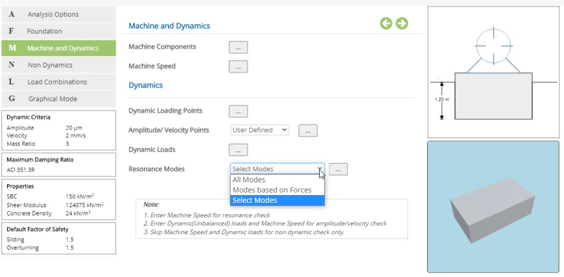
▽ All Modes: On Selecting "All Modes", program will consider all of the following as mode of vibration.
- Uncoupled Modes - Translational
- Uncoupled Modes - Rotational
- Coupled Modes
▽ Modes based on Forces: On Selecting "Modes based on Forces", program will consider the modes according to the presence of dynamic loads.
▽ Select Modes: On selecting "Select Modes", Select Mode button will be displayed.
Select Modes (Resonance Modes)
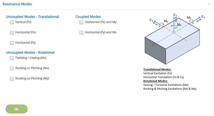
Clicking on select mode button will display the Resonance Modes pop-up. This pop-up will display list of all the possible modes of vibration to be considered. Select the modes of vibration which are to be considered for the analysis.
Non Dynamics
This page allows to define the non-dynamic load cases, loading points and loads.
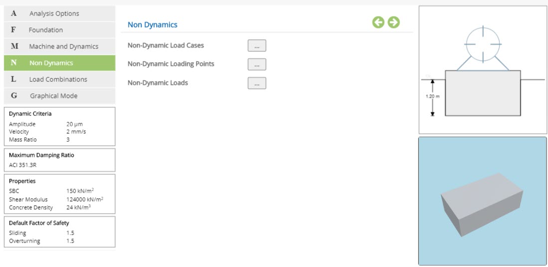
The following buttons are provided for pop-up dialog for the input data:
- Non-Dynamic Load Cases
- Non-Dynamic Loading Points
- Non-Dynamic Loads
Non-Dynamic Load Cases
Click this button to open the non-dynamic load cases pop-up dialog. This is a spreadsheet type input dialog - right click to add or delete rows. Alternatively, the user can copy and paste the data from external source such as Microsoft Excel.
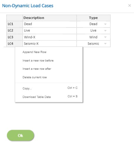
In this pop-up, n - number of load cases and its Type can be defined.
Description
Enter the description of the load case. While the description can be duplicated across various cases, this is not advised since it is used as a reference to define load combinations. This field cannot be left blank and the special character '#'cannot be used.
Type
Select the load type Dead, Live, Wind, Seismic, Emergency, Maintenance, Abnormal, Operation or Other. First load case type should be always 'Dead'.
- Note: Any row deletion, addition and modification will affect the load combinations and non-dynamic loads.
Non-Dynamic Loading Points
Click this button to open the Non-Dynamic Loading Points pop-up dialog. This is a spreadsheet type input dialog where rows can be deleted or added. The user can also copy and paste the data from an external source such as Microsoft Excel.
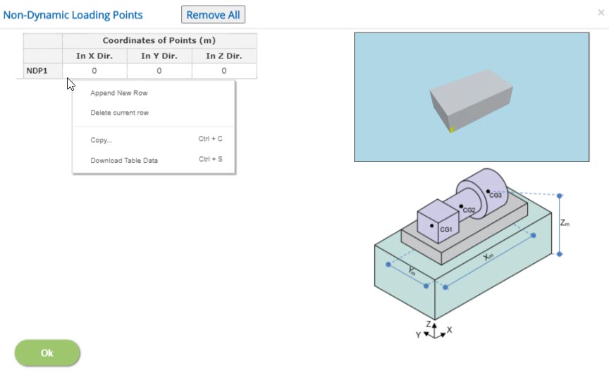
Coordinates of Points
Enter the X, Y and Z coordinates value from the origin at which the non-dynamic loads are acting.
Non-Dynamic Loads
Click this button to open the non-dynamic loads pop-up dialog. This is a spreadsheet type input dialog where rows can be deleted or added. The user can also copy and paste the data from an external source such as Microsoft Excel.
Forces
Enter the forces acting in the selected loading point in corresponding X, Y and Z directions.
↔ Range: -100000 to 100000 kN
Moment
Enter the moments acting in the selected loading point in corresponding X, Y and Z directions.
↔ Range: -100000 to 100000 kNm
- Note: Non-dynamic loads are not applicable, when non-dynamic loading points are not defined.
Loads Combinations
This page allows to define the service load combinations with dynamic and non-dynamic loadings and allowable factors for percentage change in safe bearing capacity, overturning and sliding are defined in this page.
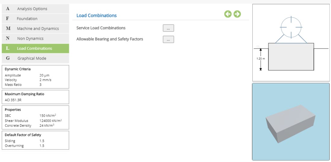
The following buttons are provided for the pop-up dialog to input the data.
- Service Load Combinations
- Allowable Bearing and Safety Factors
Service Load Combinations
Click this button to open the Service load Combinations pop-up dialog. This is a spreadsheet type input dialog - right click to add or delete rows. Alternatively, user can copy and paste the data from an external source such as Microsoft Excel.
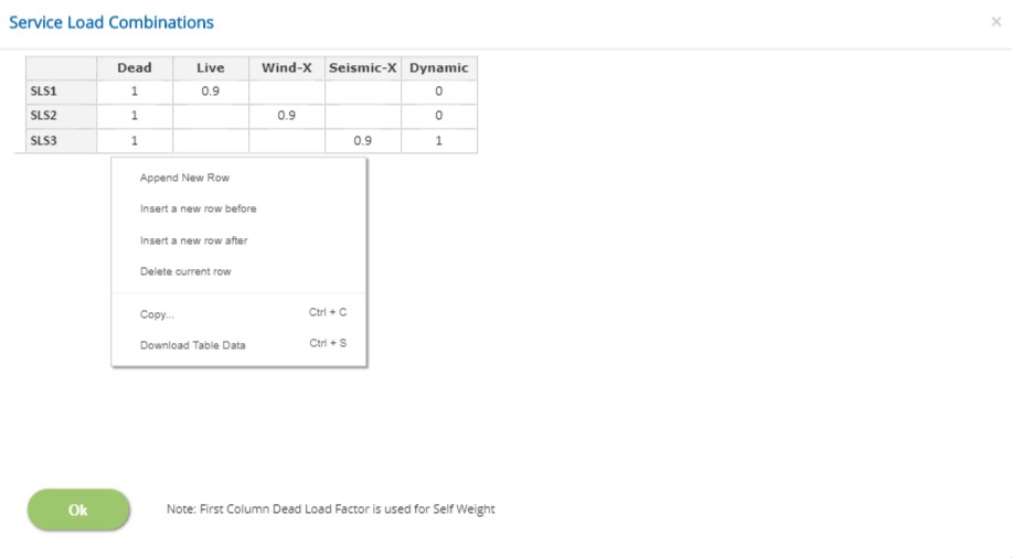
In this pop-up, n - number of load combinations can be generated by defining different load factors.
Load Cases Factors
Load case descriptions are displayed in each spreadsheet column. This pop-up consists of factors for both dynamic and non-dynamic load cases.
↔ Range: -5 to 5
- Note: For Dead Load case, which is the first column, the factor should be a positive non-zero value.
Allowable Bearing and Safety Factors
Click this button to open the allowable factors pop-up dialog. This is a spreadsheet type input dialog but rows cannot be deleted or added. The user can also copy and paste the data from an external source such as Microsoft Excel.
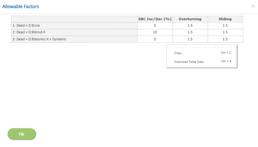
The first column header displays the service load combination according to the load factors defined in the service load combinations.
SBC Inc/Dec (%):
Enter the percentage of increase / decrease of safe bearing capacity for each service load combination. Negative value indicates decrease in allowable value.
↔ Range: -100 to 200 %
Overturning / Sliding
Enter the allowable factor of safety for the stability checks.
↔ Range: 1 to 10
Graphical Mode
The base block and the pedestal geometry can also be modelled visually in Graphical Mode. Graphical Edit mode is invoked by clicking the Graphical Mode menu.
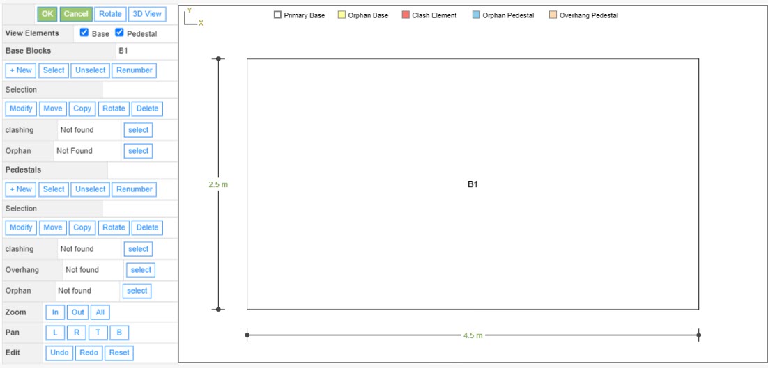
Click the base block or pedestal geometry on the picture to select and make the modification using the buttons given on the left side.
Buttons are provided for group selection, copying, rotating the base block and pedestals.
The buttons L Left, R Right, B Bottom and A All can be used to pan through the model.
The buttons Undo , Redo and Reset are used to undo, redo or reset the recent changes.
- Note: If the picture is not fully visible, click on the Zoom All button.
Graphical Mode - 3D View
Click on the "3D view" button to display the 3D view of the foundation developed.
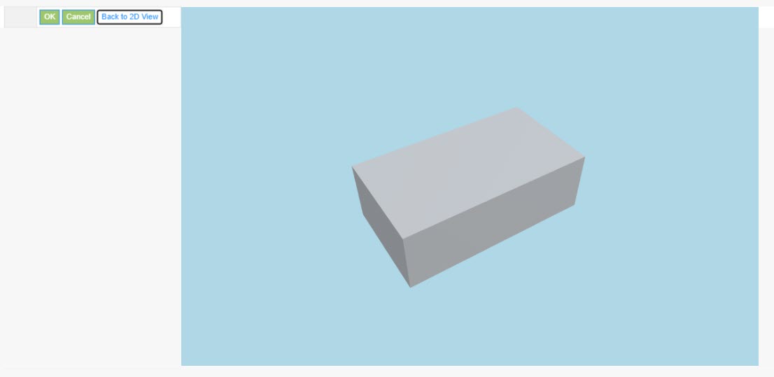
Options to edit is not available in 3D view. In order to make a change, use 'Back to 2D View' button.
Settings
Setting for various Analysis data such as Dynamic criteria, Damping ratios, Soil and Concrete properties, and safety factors are presented in this section. This setting pop-up can be accessed by clicking the bottom panel below the left navigation.
Dynamic Criteria
Enter the permissible limits for no resonance, amplitude, velocity, mass ratio, eccentricity and degree step for time history analysis.
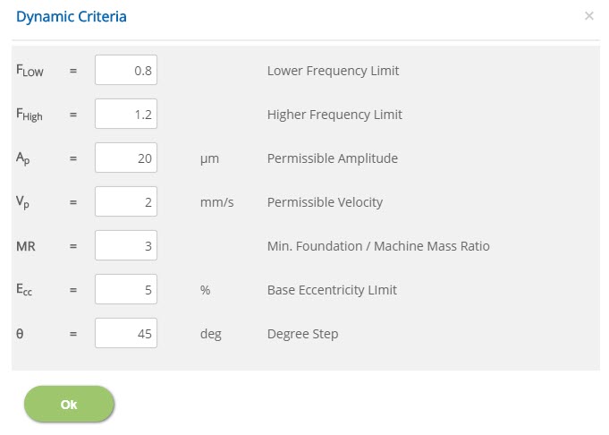 Lower Frequency Limit
↔ Range: 0.1 to 1
Higher Frequency Limit↔ Range: 1 to 2
Permissible Amplitude↔ Range: 0.1 to 500 μm
Permissible Velocity↔ Range: 0.1 to 100 mm/s
Minimum Foundation / Machine Mass Ratio↔ Range: 1 to 10
Base Eccentricity Limit↔ Range: 1 to 10 %
Degree StepDegree step is converted in to time step for Time history analysis.
↔ Range: 1 to 360 deg
Maximum Damping Ratio
Enter the maximum damping ratio in vertical, horizontal and rotational motion in the corresponding directions.
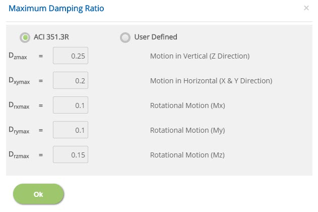
☉ACI 351.3R: Select this option to use Damping ratio as per ACI 351.3R.
☉User Defined: Select this option to enter the maximum damping ratio.
↔ Range: 0.01 to 0.5
Motion in Horizontal (X & Y Direction)↔ Range: 0.01 to 0.5
Rotational Motion (Mx)↔ Range: 0.01 to 0.5
Rotational Motion (My)↔ Range: 0.01 to 0.5
Rotational Motion (Mz)↔ Range: 0.01 to 0.5
Properties
Enter the properties of materials such as soil and concrete in this properties pop-up dialog.
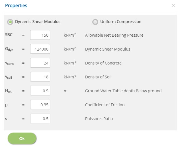
☉Dynamic Shear Modulus: Dynamic shear modulus is applicable for Richard - Lysmer method. If user enters this value in Barkan's method, the program will convert dynamic shear modulus into uniform compression.
↔ Range: 10000 to 500000 kN/m2
☉Uniform Compression: Dynamic shear modulus is applicable for Barkan's method. If user enters this value in Richard - Lysmer's method, the program will convert uniform compression into dynamic shear modulus.
↔ Range: 500 to 75000 kN/m3
↔ Range: 25 to 1000 kN/m2
Coefficient of Uniform Compression↔ Range: 500 to 75000 kN/m3
Density of Concrete / Soil↔ Range: 10 to 40 kN/m3
Ground Water Table depth Below ground↔ Range: 0 to 10 m
Coefficient of Friction↔ Range: 0.05 to 1.5
Poisson's Ratio↔ Range: 0.2 to 1
Factor of Safety
Enter the factor of safety against sliding and overturning in this pop-up.
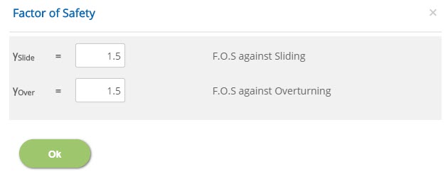 F.O.S against Sliding / Overturning
↔ Range: 1 to 5
Error Handling
Errors and Warnings are generated to prevent any inadvertent error in the input data. This section describes how to handle the errors and warnings. These errors are displayed at the bottom of the input page when the data in one or more input fields invalidate each other.
- Note: Out of range errors are displayed next to the input field.
| # | Error | Reason | Solution |
|---|---|---|---|
| 1 | Warning : Clashing Base Blocks found | One or more base blocks are clashing with each other. | Care should be taken so that no base blocks would clash with each other. |
| 2 | Warning : Disjointed Base Blocks found | One or more base blocks are found to be disjointed. | Care should be taken so that base blocks are jointed with each other. |
| 3 | Warning : Clashing Pedestals found | One or more pedestals are clashing with each other. | Care should be taken so that no pedestals would clash with each other. |
| 4 | Warning : Overhanging pedestal(s) - not fully supported on Base Block(s) | One or more pedestals overhanging or not fully supported on base block. | Care should be taken so that pedestals are properly supported on base block without any overhanging. |
| 4 | Warning : Orphan pedestal(s) - not supported on Base Block(s) | One or more orphan pedestals are not supported on base block. | Care should be taken so that orphan pedestals are properly supported on base block. |