Help Topics
ECGANTRY - Crane Gantry Girder Design
This part of user manual describes how to use ECGANTRY for the design of Crane Gantry Girder. ECPlus applications are designed as wizard type which is a step by step guided input procedure. If you are new to ECPlus applications, click here for general guidance.
Prerequisites: The user is expected to have a basic understanding of structural analysis and steel design concepts.
The minimum input data required to use this application is as follows:
- ❶ Structural Steel Section and Grade.
- ❷ Span and Restraint Conditions.
- ❸ Wheel Loads or Crane Details.
Gantry Girder
This page allows to select the span and section details for the crane gantry girder.
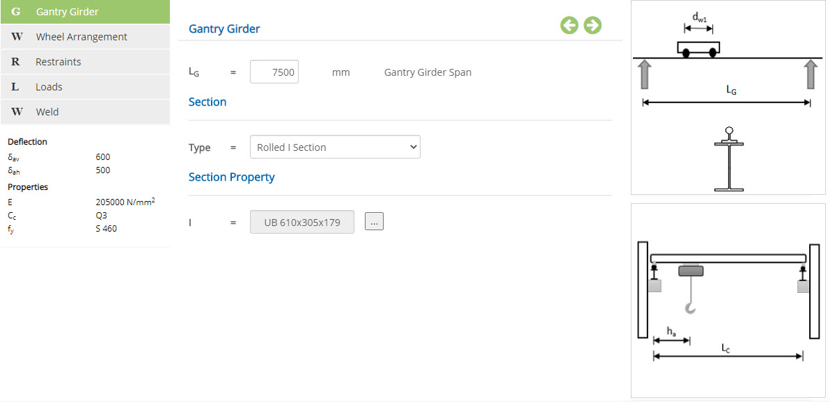
Gantry Girder Span - LG
Enter the span of the gantry girder.
↔ Range: 1000 to 20000 mm
Type
Select the section profile for the gantry girder.
▽ Rolled I Section: Select this if gantry section profile is a standard I section.
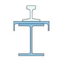
▽ Rolled I Section + Channel: Select this if gantry section profile is a combined standard I section and a cap channel.
▽ Rolled I Section + Plate: Select this if gantry section profile is a combined standard I section and a cap plate.
▽ Welded I Section: Select this if gantry section profile is an I shape fabricated with plates.
Section Property
To select the applicable standard I / Channel section for the types, Rolled I Section or Rolled I Section + Channel or Rolled I Section + Plate, click button, to open pop-up section dialog.
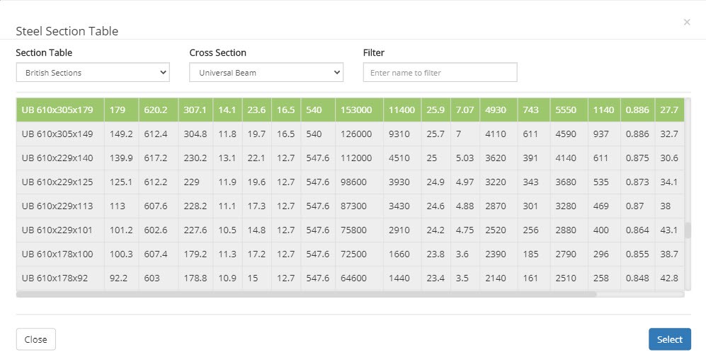
Section Table
Select the steel table from the list ▽ British Section ▽ European Section and ▽ AISC Section.
Cross Section
Select the section designation listed for the selected table above.
Filter
Enter the keyword to display the sections matching with.
To define the plate dimensions for the type ▽ Rolled I Section + Plate:
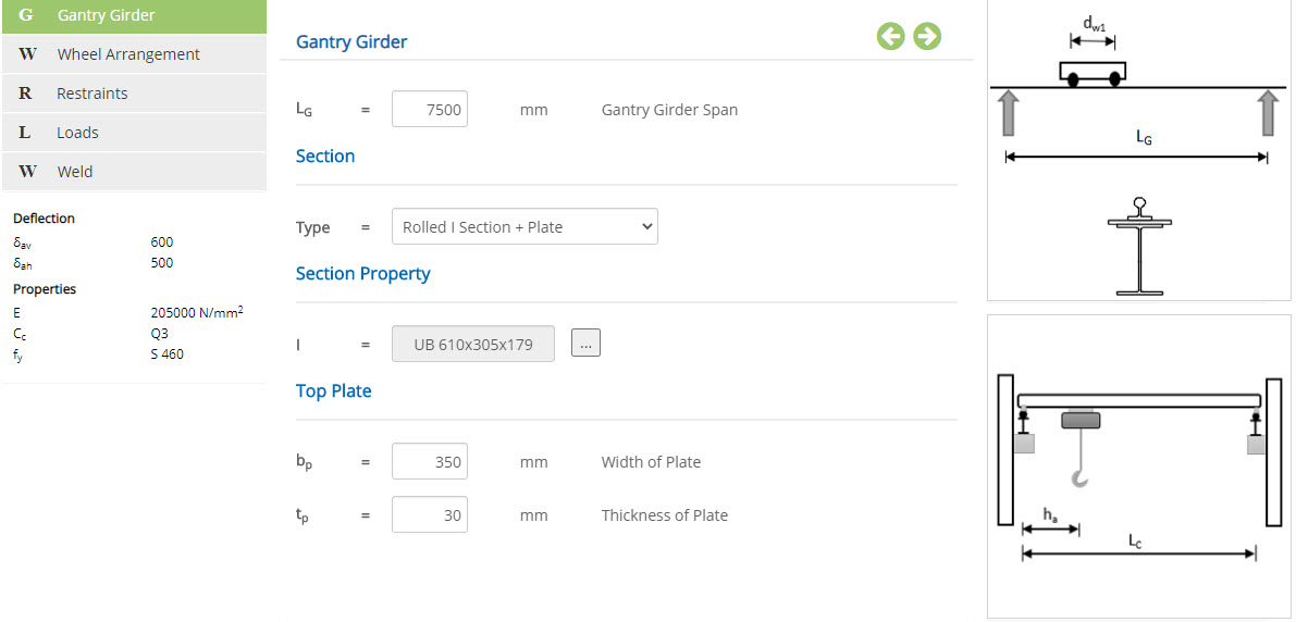
Width of Plate - bp
Enter the width of the plate.
↔ Range: 50 to 1000 mm
Thickness of Plate - tp
Enter the thickness of the plate.
↔ Range: 1 to 50 mm
To define the I section for the type ▽ Welded I Section:
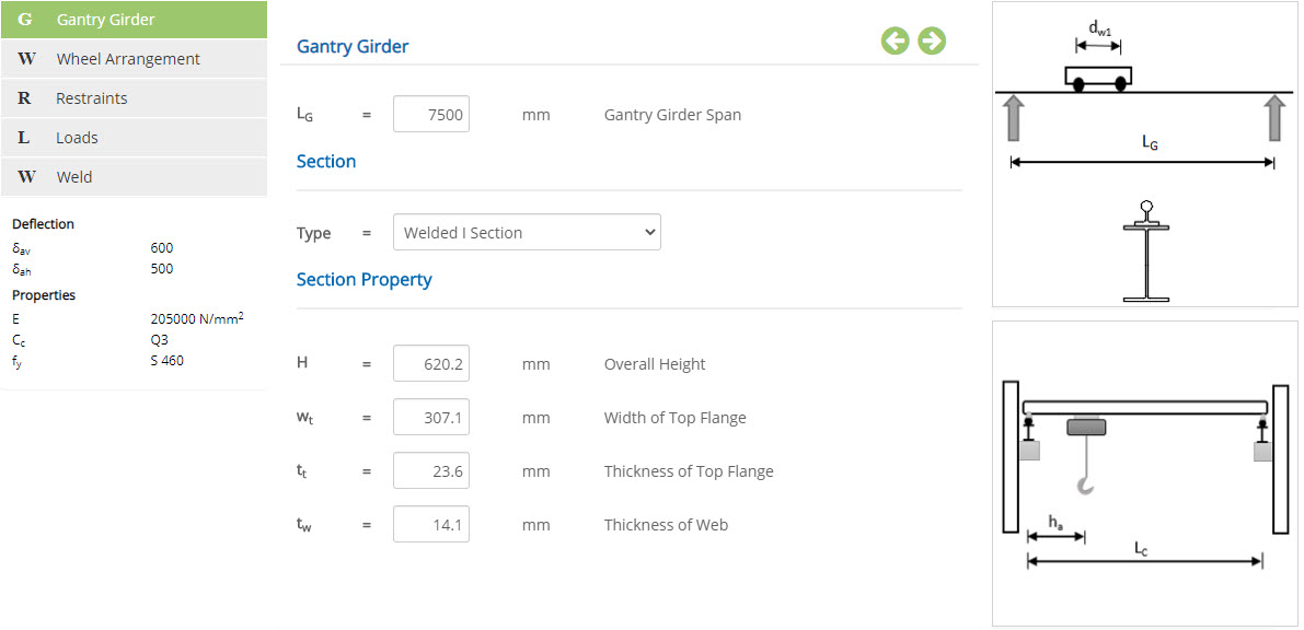
Overall Height - H
↔ Range: 100 to 1500 mm
Width of Top Flange - wt
↔ Range: 100 to 1500 mm
Thickness of Top Flange - tt
↔ Range: 3 to 25 mm
Thickness of Web - tw
↔ Range: 3 to 25 mm
Wheel Arrangement
This page allows to define the wheel arrangement such as number of wheels and their spacing.
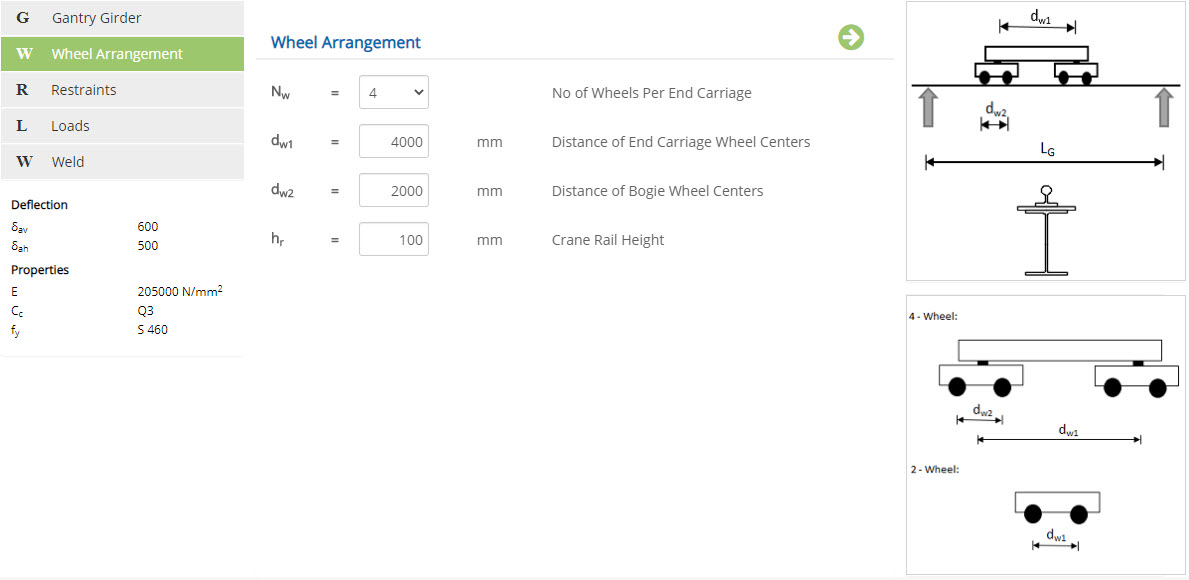
No of Wheels per End Carriage - Nw
Select the number of wheels: ▽ 2 or ▽ 4.
Distance of End Carriage Wheel Centers - dw1
Enter the centre to centre distance between the wheels within the bogie.
↔ Range: 500 to 8000 mm
Distance of Bogie Wheel Centres
Enter the centre to centre distance of bogies (For ▽ 4 wheel arrangement).
↔ Range: 100 to 5000 mm
Crane Rail Height - hr
Enter the overall height of the crane rail.
↔ Range: 10 to 500 mm
Restraints
This page allows to select the support restraint condition for effective length calculation.

Restraints
☐ Destabilizing
Check this option, if loading condition on the section is not normal (Destabilizing).
▽ Restraint Condition
Select a predefined restraint condition or User Defined to specify effective length factor of the girder.
Effective Length Factor (For User Defined)
↔ Range: 0.5 to 2
| Conditions at restraints at supports | Loading Condition | ||
|---|---|---|---|
| Normal | Destabilizing | ||
Compression Flange Laterally Restrained. | Both flanges fully restrained against rotation on plan. | 0.7L LT | 0.85LLT |
| Compression flange fully restrained against rotation on plan. | 0.75L LT | 0.9LLT | |
| Both flanges partially restrained against rotation on plan. | 0.8L LT | 0.95LLT | |
| Compression flange partially restrained against rotation on plan. | 0.85L LT | 1.0LLT | |
| Both flanges free to rotate on plan. | 1.0L LT | 1.2LLT | |
| Compression Flange Laterally Unrestrained. | Partial torsional restraint against rotation about longitudinal axis provided by connection of bottom flange to supports. | 1.0LLT + 2D | 1.2LLT + 2D |
| Partial torsional restraint against rotation about longitudinal axis provided only by pressure of bottom flange onto supports. | 1.2LLT + 2D | 1.4LLT + 2D | |
| D is the overall depth of the beam. | |||
Span Type
The position of the span affects the moving load analysis.
☉End Span: This option allows to select the position of the span. Moving load analysis will be affected based on the position of span.
☉Interior Span: Select this option for the intermediate span.
Loads
This page allows to enter the crane loads.
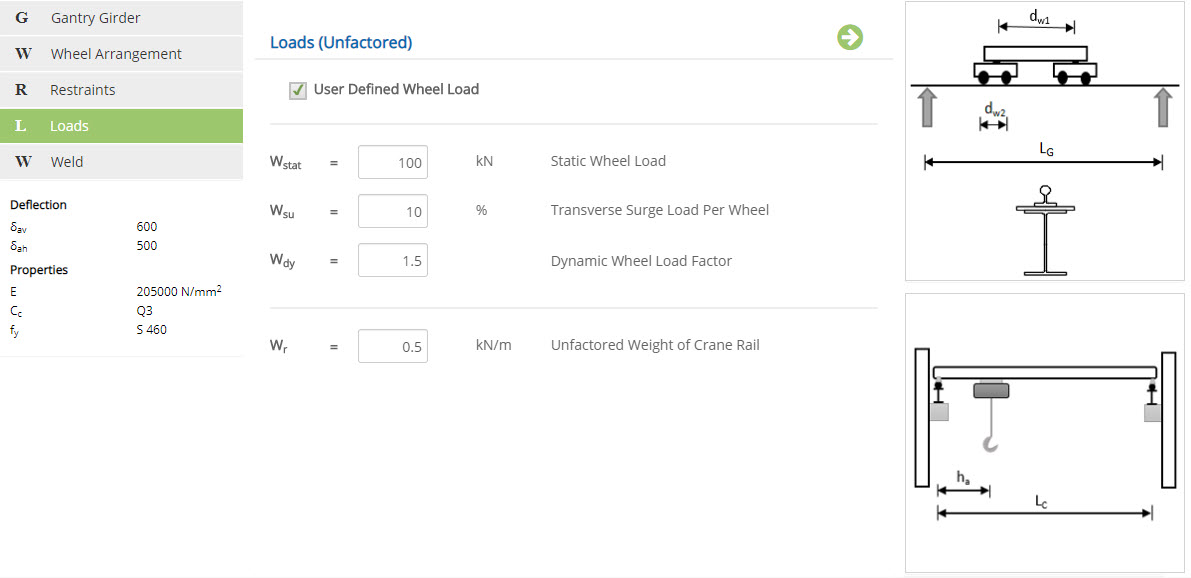
☐ User Defined Wheel Load
Check this to enter wheel loads directly or uncheck to define the crane arrangement and loads to be calculated by the program.
Static Wheel Load - Wstat
Enter the wheel load without any dynamic factor.
↔ Range: 1 to 10000 kN
Transverse Surge Load Per Wheel - Wsu
↔ Range: 1 to 100 %
Dynamic Wheel Load Factor - Wdy
↔ Range: 1 to 5
Enter the values below for the user defined crane arrangement:
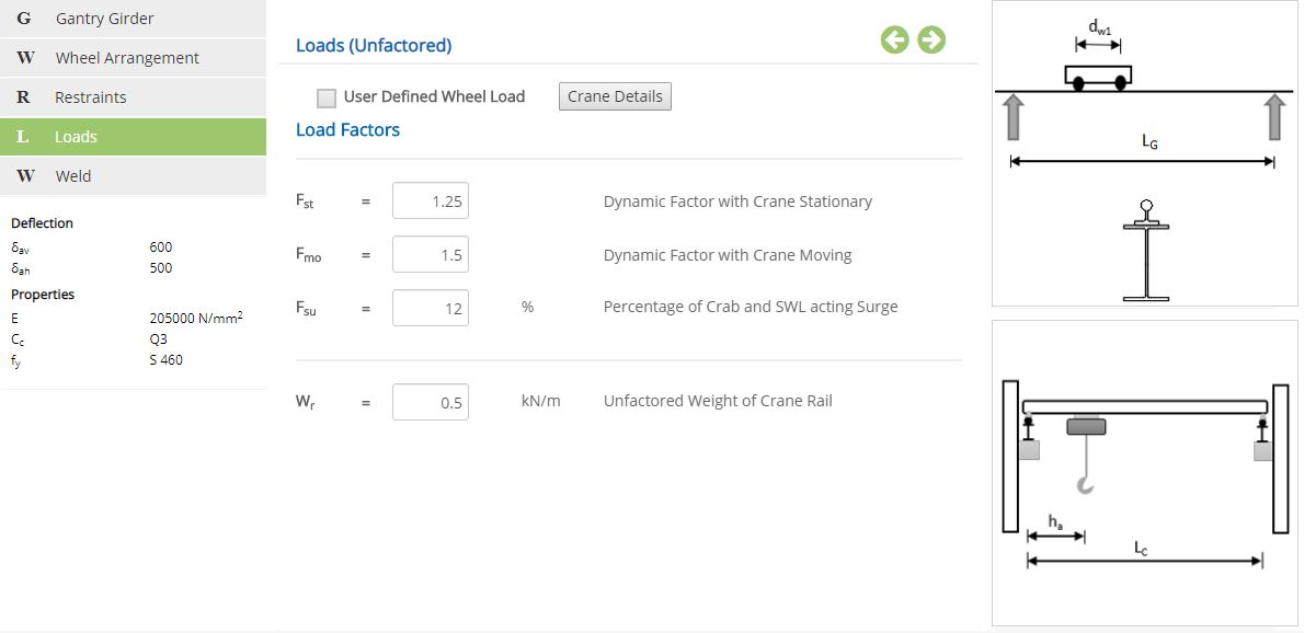
Dynamic Factor with Crane Stationary - Fst
Enter the dynamic factor for the load being lifted without moving.
↔ Range: 0.5 to 3
Dynamic Factor with Crane Moving - Fmo
Enter the dynamic factor for the moving crane with load.
↔ Range: 0.5 to 3
Percentage of Crab and SWL acting Surge - Fsu
↔ Range: 0 to 50 %
Unfactored Weight of Crane Rail - Wr
↔ Range: 0.1 to 50 kN/m
Crane Details
Click this button to open the crane details pop-up dialog and define the crane arrangement and enter unfactored loads.
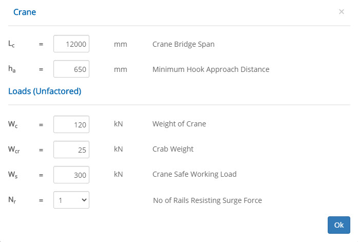
Crane Bridge Span - Lc
↔ Range: 1000 to 20000 mm
Minimum Hook Approach Distance - ha
↔ Range: 500 to 5000 mm
Weight of Crane - Wc
↔ Range: 1 to 10000 kN
Crab Weight - Wcr
↔ Range: 0 to 5000 kN
Crane Safe Working Load - Ws
↔ Range: 10 to 10000 kN
No of Rails Resisting Surge Force - Nr
Select whether one or two rails are resisting the surge force.
Weld
Weld properties are applicable only for I Section with Channel or Plate.
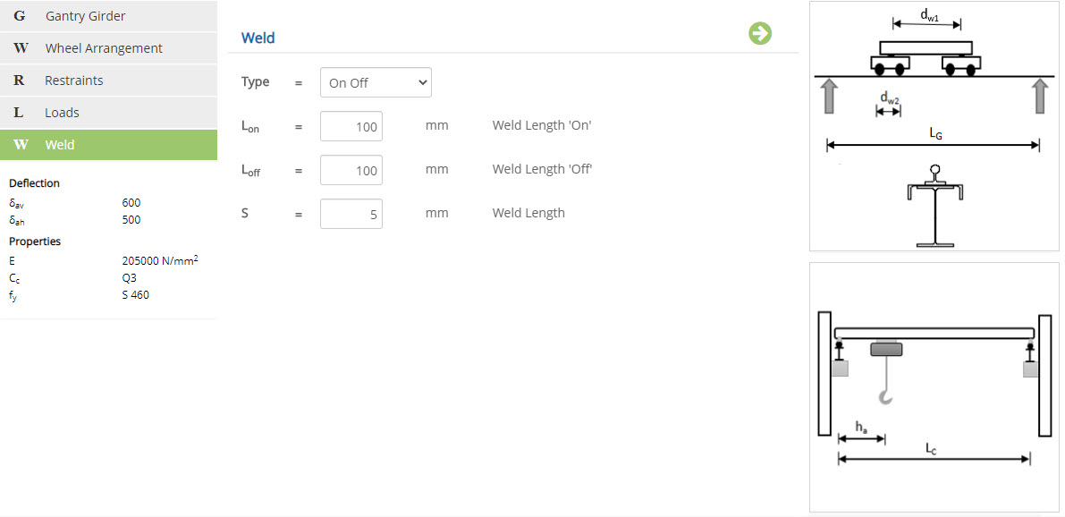
Type
Select the type of weld as
▽ Continuous
▽ On Off : (Intermittent weld)
Weld Length 'On' - Lon
Enter the length of the continuous weld.
↔ Range: 10 to 1000 mm
Weld Length 'Off' - Loff
Enter the gap between the welds.
↔ Range: 10 to 1000 mm
Weld Thickness - S
Enter the thickness of the weld.
↔ Range: 1 to 20 mm
Design Setting
Setting for various Design Data such as Deflection limits, Modulus of Elasticity, Class of Crane and Steel Grade are presented in this section. This setting pop-up can be accessed by clicking the bottom panel below the left navigation.
Deflection
Enter the limits for deflection in both vertical and horizontal directions.
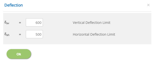
Vertical Deflection Limit - δav
↔ Range: 100 to 300
Horizontal Deflection Limit - δah
↔ Range: 100 to 300
Properties
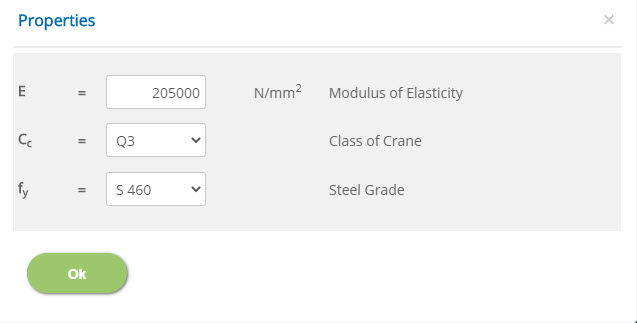
Modulus of Elasticity - E
↔ Range: 100000 to 500000 N/mm2
Class of Crane - Cc
Select the class of crane:
▽ Q1: Cranes which hoist the SWL very rarely and normally, light loads.
▽ Q2: Cranes which hoist the SWL fairly frequently and normally, heavy loads.
▽ Q3: Cranes which hoist the SWL frequently and normally, heavy loads.
▽ Q4: Cranes which are normally loaded close to the SWL.
Steel Grade - fy
Select the grade of steel for the gantry girder section.
- Note: Class of crane is defined as per BS2573-1:1983.
Error Handling
Errors and Warnings are generated to prevent any inadvertent error in the input data. This section describes how to handle the errors and warnings. These errors are displayed at the bottom of the input page when the data in two or more input fields invalidate each other.
- Note: Out of range errors are displayed next to the input field.
| # | Error | Reason | Solution |
|---|---|---|---|
| 1 | Error : Depth of Channel must be Greater than I Section Width | When section type selected is Rolled I Section + Channel, the cap channel depth is insufficient to accommodate the main I section flange width. | Select the channel section sufficiently wide enough to accommodate the width of I section. |
| 2 | Error : Width of Plate should be Greater than Width of I Section | When section type selected is Rolled I Section + Plate, the cap plate depth is lesser than the main I section flange width. | Use wider plate size. |
| 3 | Error : Distance of Bogie Wheel Centers Should be Less than the End Carriage Wheels | When four wheel arrangement is selected, the distance between the bogie has been entered less than the wheel centers. | Make sure that the bogie distance is greater than the wheel centers. |
| 4 | Error : Minimum Hook Approach Should be Less than the Half the Span of Crane Bridge | Minimum hook approach has been defined such that for the defined gantry girder span, crane movement is impossible | Make sure that the minimum hook approach is well before the midspan. |