Help Topics
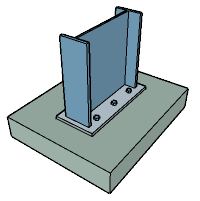
ECBASEPLATE - Column Base Plate Pinned Design
This part of user manual describes how to use ECBASEPLATE for the design of Column base plate pinned. ECPlus applications are designed as wizard type which is a step by step guided input procedure. If you are new to ECPlus applications, click here for general guidance.
Prerequisites: The user is expected to have a basic understanding of foundation design concepts.
The minimum input data required to use this application is as follows:
- ❶ Structural Steel Section and Grade
- ❷ Bolt Anchorage Details
- ❸ Plate Loads and Moment
Column
This page allows to enter column details.
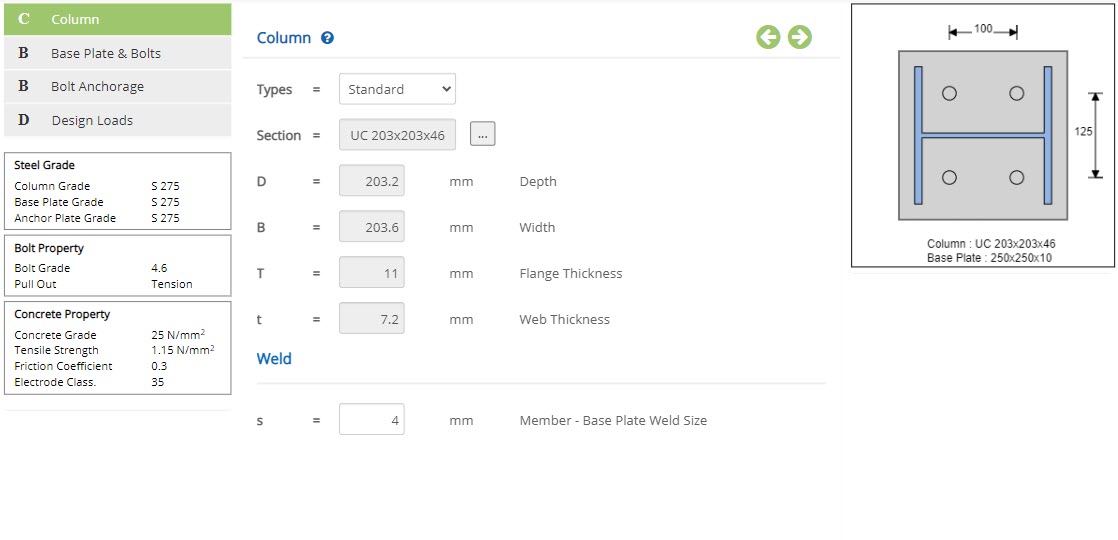 Type
TypeSelect the option between Standard, I Sec - User, RHS Sec - User or SHS Sec - User.
▽ Standard: Select this option to design base plate per British, Euro or American Standard.
▽ I Sec - User: Select this option for Base plate to assign as user defined I Section.
▽ RHS Sec - User: Select this option for Base plate to assign as user defined RHS Section.
▽ SHS Sec - User: Select this option for Base plate to assign as user defined SHS Section.
Steel Section Table
By choosing the Type as Standard , the Cross-sectional properties will be displayed for the selected Section. To change the selected Section, click button, a pop-up dialog box displays a list of standard section based on option listed in menu Section Table & Cross Section
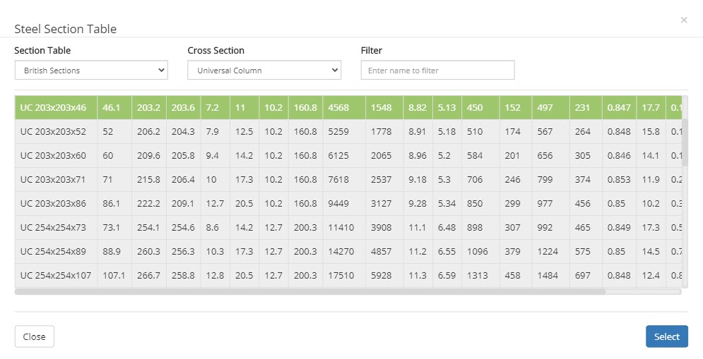 ▽ Section Table:
Select this option to have list of Standard British, European or AISC Sections.
▽ Cross Section:This option allows user to select wider or narrow flange beam like UB, UC, IPE, HE, W, M, etc., based on selection at Section Table menu.
▽ Filter:Based on name by user and with option selected at Section Table and Cross Section , a filtered member list will be displayed.
I Sec User
By choosing the Type as I Sec User , enter the Cross-sectional properties.
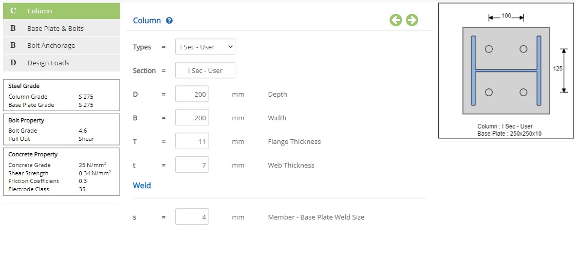 Depth - D
Enter overall depth of the section.
↔ Range: 50 to 1500 mm
Enter the flange width of the section.
↔ Range: 50 to 1500 mm
Enter the thickness of flange of the section.
↔ Range: 3 to 100 mm
Enter the thickness of web of the section.
↔ Range: 2 to 100 mm
RHS Sec User
By choosing the Type as RHS Sec User , enter the Cross-sectional properties.
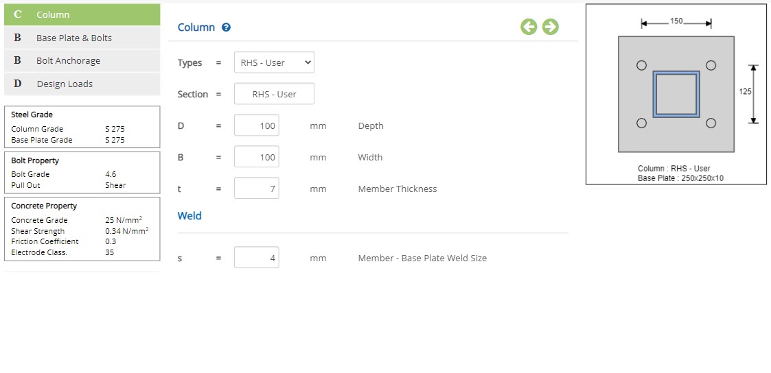 Depth - D
Enter overall depth of the section.
↔ Range: 50 to 1500 mm
Enter the flange width of the section.
↔ Range: 50 to 1500 mm
Enter the member thickness of the section.
↔ Range: 2 to 100 mm
SHS Sec User
By choosing the Type as RHS Sec User , enter the Cross-sectional properties.
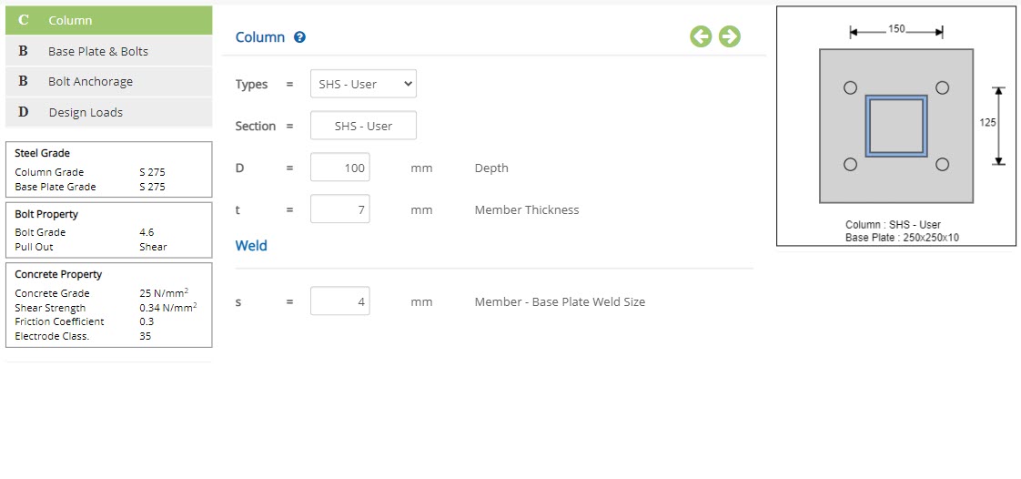 Depth - D
Enter overall depth of the section.
↔ Range: 50 to 1500 mm
Enter the member thickness of the section.
↔ Range: 2 to 100 mm
Weld
Member - Base Plate Weld Size - sEnter the weld size between member and base plate.
↔ Range: >= 0 mm
Base Plate & Bolts
This page allows to enter base plate and bolts details.
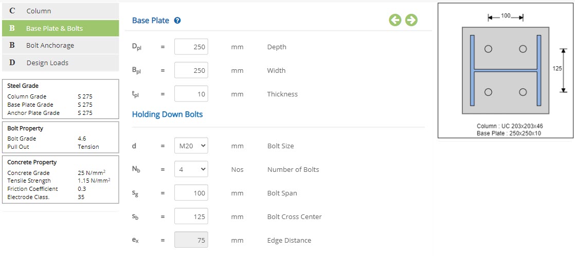
Base Plate
Depth - DplEnter the depth of the base plate.
↔ Range: 200 to 2000 mm
Enter the width of the base plate.
↔ Range: 200 to 2000 mm
Enter the thickness of the base plate.
↔ Range: 3 to 150 mm
Holding Down Bolts
Bolt Size - dSelect the size of bolt.
Number of Bolts - NbSelect the number of bolts.
Bolt Span - sgEnter the bolt span.
↔ Range: >= 0 mm
Enter the bolt cross center distance.
↔ Range: >= 0 mm
Displays the edge distance of bolts.
Bolt Anchorage
This page allows to enter bolt anchorage details.
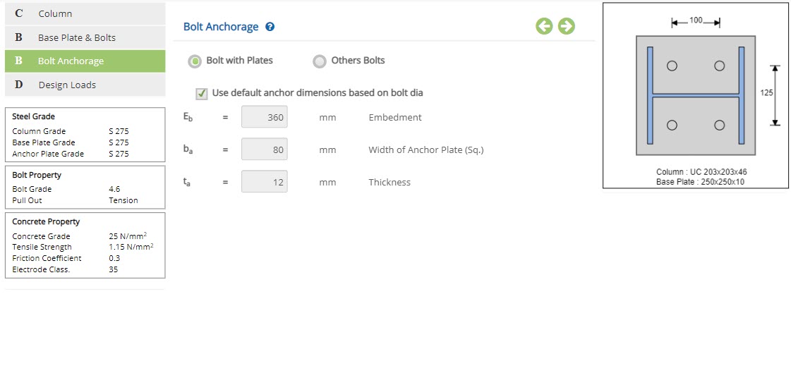
☉Bolt with Plates
Choose this option to use bolt with plates.
☉Others Bolts
Choose this option to use other bolts.
Bolt with Plates
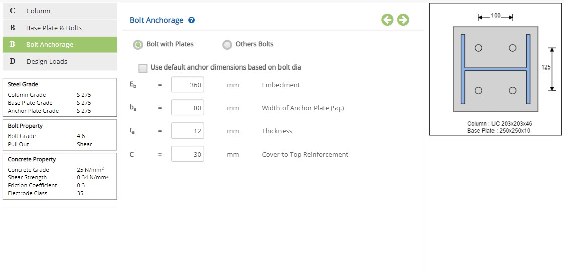
☐ Use default anchor dimensions based on bolt dia
Check this option to use default anchor dimensions based on the bolt diameter.
Enter the embedment of anchor plate.
↔ Range: 200 to 1500 mm
Enter the width of the anchor plate.
↔ Range: >= 0 mm
Enter the thickness of the anchor plate.
↔ Range: 3 to 50 mm
Enter the cover to top reinforcement.
↔ Range: 20 to 70 mm
Other Bolts
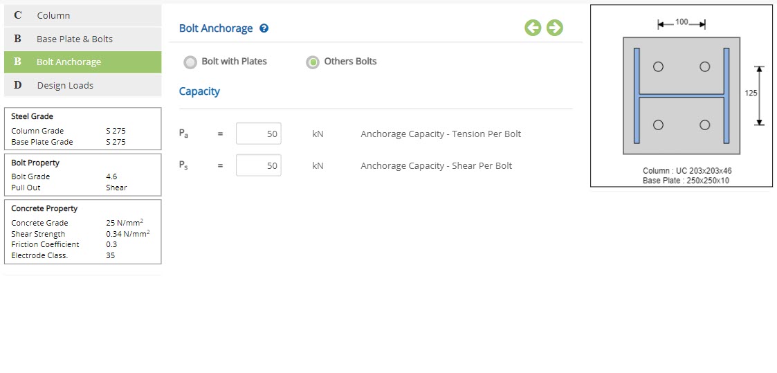 Anchorage Capacity - Tension Per Bolt - Pa
Enter the anchorage capacity tension per bolt.
↔ Range: 0 to 1000 mm
Enter the anchorage capacity shear per bolt.
↔ Range: 0 to 1000 mm
Design Loads
This page allows to enter load details.
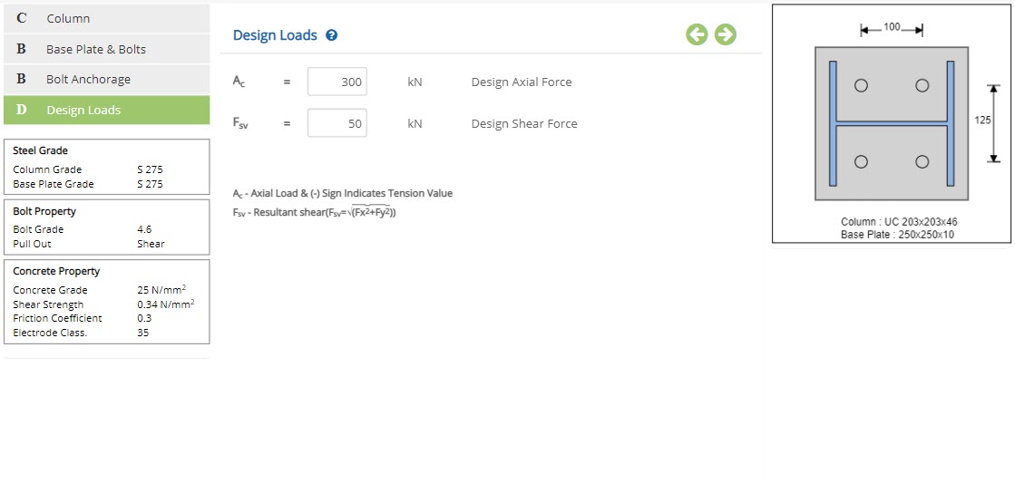 Design Axial Force - Ac
Enter the design axial load.
↔ Range: -15000 to 15000 kN
Enter the design shear force.
↔ Range: 0 to 15000 kN
Design Setting
Setting for various Design Data such as Steel grade, Characteristic and Tensile Strength of Concrete, Coefficient of Friction, Electrode Classification and Bolt Pullout Based on Concrete are presented in this section. This setting pop-up can be accessed by clicking the bottom panel below the left navigation.
Steel Grade
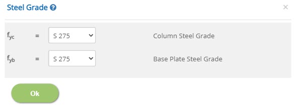 Column Steel Grade / Base Plate Steel Grade - fyc / fyb
Select the grade of steel for column and base plate.
Bolt Property
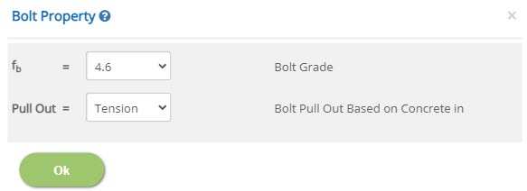 Bolt Grade - fb
Select the bolt grade.
Bolt Pull Out Based on Concrete in - Pull OutSelect whether bolt pull out based on concrete in tension or shear.
Concrete Property
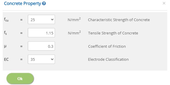 Characteristic Strength of Concrete - fcu
Select the characteristic strength of concrete.
Tensile Strength of Concrete - fs (Pull Out = Tension)↔ Range: >= 0.01 N/mm2
Shear Strength of Concrete - vc (Pull Out = Shear)↔ Range: TODO
Coefficient of Friction - µ↔ Range: 0 to 1
Electrode Classification - ECSelect the electrode classification.
Error Handling
Errors and Warnings are generated to prevent any inadvertent error in the input data. This section describes how to handle the errors and warnings. These errors are displayed at the bottom of the input page when the data in one or more input fields invalidate each other.
- Note: Out of range errors are displayed next to the input field.
| # | Error | Reason | Solution |
|---|---|---|---|
| 1 | Warning : The bolts lie at an angle greater than 45 degrees of line drawn from the outer edge of column flange | Bolts provided lies at an angle greater than 45 degrees of line drawn from outer edge of flange of the column. | Bolt should be provided such that it lies with 45 degrees of line drawn from outer edge of flange of column. |
| 2 | Warning : Flange - Base Plate Weld Size should not exceed 3 mm | Size of weld between flange and base plate is greater than 3 mm. | Size of weld between flange and base plate should be lesser than 2 mm. |
| 3 | Warning : Web - Base Plate Weld Size should not exceed 3 mm | Size of weld between web and base plate is greater than 3 mm. | Size of weld between web and base plate should be lesser than 2 mm. |
| 4 | Error : Section Depth (D) must be less than Base Plate Depth (Dpl) | Depth of the section is greater than the depth of the base plate. | Increase depth of the base plate or decrease depth of the section. |
| 5 | Error : Section Depth (D) must be greater than 200 | Depth of the section provided is lesser than 200 mm. | Provide depth of the section greater than 200 mm. |
| 6 | Error : Section Width (B) must be less than Base Plate Width (Bpl) | Width of the section is greater than the width of the base plate. | Increase the width of the base plate or increase the width of the section. |
| 7 | Error : Section Width (B) must be greater than 200 | Width of the section provided is lesser than 200 mm. | Provide width of the section greater than 200 mm. |
| 8 | Error : Bolt Span cannot be negative | Negative value is provided for the bolt span. | Enter a positive value for the bolt span. |
| 9 | Error : Minimum gauge for successive bolts should be 5 times bolt diameter | Gauge for successive bolts is lesser than the 5 times bolt diameter. | Increase gauge or decrease bolt diameter, such that gauge is greater than or equal to 5 times bolt diameter. |
| 10 | Error : The base plate is not wide enough to accommodate specified number of bolts | Specified number of bolts are not able to accommodate within the width of the base plate. | Increase the width of base plate or decrease the number of bolts provided. |
| 11 | Error : The bolts must lie within a line drawn at 50 degrees from the outer edge of the column flange | Bolts lies away from the line drawn 50 degrees from the outer edge of the column flange. | Locate the bolts such that it lies within the line drawn at 50 degrees from the outer edge of the column flange. |
| 12 | Error : There is a clash between the bolt nuts and the column web | Clash has occurred between the bolt nuts and column web. | Care should be taken such that there is no clash between the bolt nuts and column web. |
| 13 | Error : Insufficient clearance between bolt and web | There is an insufficient clearance between bolt and web. | Clearance should be provided sufficient enough between bolt and web. |
| 14 | Error : Vertical edge distance is less than the minimum allowable (1.5 * d), Hence decrease the bolt spacing | Vertical edge distance provided is lesser than the allowable limit. | Provide vertical edge distance greater than the allowable limit (1.5 * d). |
| 15 | Error : Horizontal edge distance is less than the minimum allowable (1.5 * d), Hence decrease the bolt spacing | Horizontal edge distance provided is lesser than the allowable limit. | Provide horizontal edge distance greater than the allowable limit (1.5 * d), by decreasing bolt spacing. |
| 16 | Error : There is a clash between the bolt nuts and the column flange | Clash has occurred between the bolt nuts and column flange. | Care should be taken such that there is no clash between the bolt nuts and column flange. |
| 17 | Error : The bolts lie beyond the column section center | Bolt provided lies beyond the center of the column section. | Locate the bolt such that it lies within the center of the column section. |
| 18 | Error : Bolts cannot lie inside the column flange | Bolts are located inside the flange of the column. | Care should be taken to locate the bolts outside the flange of the column. |
| 19 | Error : Insufficient clearance between bolt and flange | There is an insufficient clearance between bolt and flange. | Clearance should be provided sufficient enough between bolt and flange. |
| 20 | Error : Tensile strength of concrete cannot be greater than 0.7 * √(fcu) | Tensile strength of concrete is greater than the allowable limit. | Provide tensile strength of concrete within the allowable limit. |
| 21 | Error : Bolts cannot lie beyond column flange | Bolts are located beyond the flange of the column. | Care should be taken to locate the bolts within the flange of the column. |